Section 4 - ADJUSTMENTS & REPAIR
WARNING
DO NOT attempt any adjustments, maintenance, service
or repairs with the engine running. Stop engine. Stop
blade. Engage parking brake. Remove key. Remove
spark plug wire from spark plug and secure away from
plug. Engine and components are HOT. Avoid serious
burns, allow all parts to cool before working on machine.
Fuel Filler Cap and Vent must be closed securely to
prevent fuel spillage. Once blade is disengaged, it should
come to a complete stop in 3 seconds or less. If the
blade continues to rotate after 3 seconds, the blade
brake must be adjusted. Refer to Section “BLADE
BRAKE ADJUSTMENT” for adjustment procedures or
return machine to an authorized SNAPPER dealer for
adjustment. DO NOT CONTINUE to operate machine
until blade brake is adjusted and functioning properly.
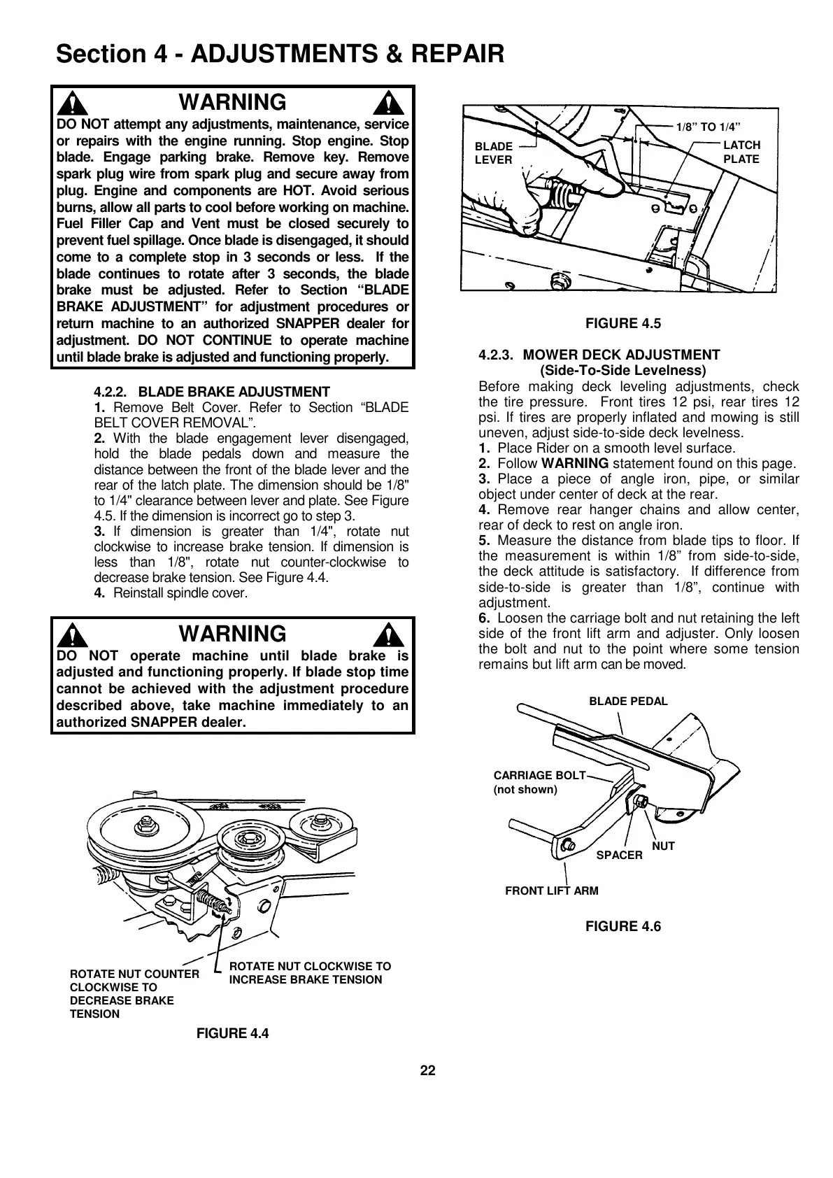
4.2.2. BLADE BRAKE ADJUSTMENT
1. Remove Belt Cover. Refer to Section “BLADE
BELT COVER REMOVAL”.
2. With the blade engagement lever disengaged,
hold the blade pedals down and measure the
distance between the front of the blade lever and the
rear of the latch plate. The dimension should be 1/8"
to 1/4" clearance between lever and plate. See Figure
4.5. If the dimension is incorrect go to step 3.
3. If dimension is greater than 1/4", rotate nut
clockwise to increase brake tension. If dimension is
less than 1/8", rotate nut counter-clockwise to
decrease brake tension. See Figure 4.4.
4. Reinstall spindle cover.
WARNING
DO NOT operate machine until blade brake is
adjusted and functioning properly. If blade stop time
cannot be achieved with the adjustment procedure
described above, take machine immediately to an
authorized SNAPPER dealer.
FIGURE 4.4
FIGURE 4.5
4.2.3. MOWER DECK ADJUSTMENT
(Side-To-Side Levelness)
Before making deck leveling adjustments, check
the tire pressure. Front tires 12 psi, rear tires 12
psi. If tires are properly inflated and mowing is still
uneven, adjust side-to-side deck levelness.
1. Place Rider on a smooth level surface.
2. Follow WARNING statement found on this page.
3. Place a piece of angle iron, pipe, or similar
object under center of deck at the rear.
4. Remove rear hanger chains and allow center,
rear of deck to rest on angle iron.
5. Measure the distance from blade tips to floor. If
the measurement is within 1/8” from side-to-side,
the deck attitude is satisfactory. If difference from
side-to-side is greater than 1/8”, continue with
adjustment.
6. Loosen the carriage bolt and nut retaining the left
side of the front lift arm and adjuster. Only loosen
the bolt and nut to the point where some tension
remains but lift arm can be moved.
FIGURE 4.6
ROTATE NUT CLOCKWISE TO
INCREASE BRAKE TENSION
ROTATE NUT COUNTER
CLOCKWISE TO
DECREASE BRAKE
TENSION
BLADE
LEVER
1/8” TO 1/4”
LATCH
PLATE
BLADE PEDAL