Section 1 - FAMILIARIZATION
J"/ _ '
PARK
_. BRAKE
DOWN PEDAL
•.................................................................................................................................................................... =
CUTTING HEIGHT
ADJUSTMENTLEVER
SEAT
ADJUSTMENT
KNOB
SPEED
CONTROL_
LEVER
OPERATOR'S
SEAT
BATTERY
(UNDER SEAT)
: CONTROL PANEL
STEERING
KEY
ENGINE SPEED
CONTROL
"% .........................................................................
DASHBOARD
CONTROLS
FUEL TANK
(UNDER HOOD)
HOOD
OVERRIDE
LEVER
BLADE
ENGAGEMENT
LEVER
DISCHARGE DEFLECTOR
HEADLIGHTS
MOWING DECK (33" SHOWN)
ENGINE
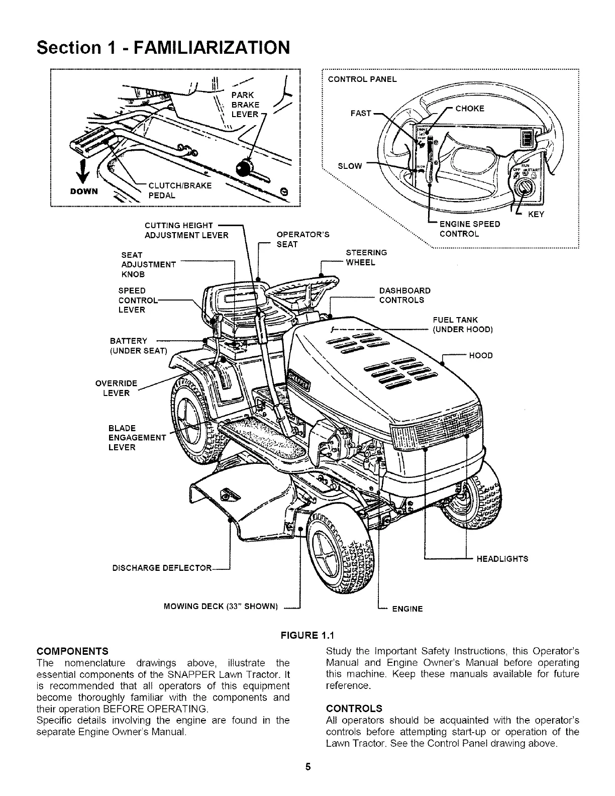
FIGURE 1.1
COMPONENTS
The nomenclature drawings above, illustrate the
essential components of the SNAPPER Lawn Tractor. It
is recommended that all operators of this equipment
become thoroughly familiar with the components and
their operation BEFORE OPERATING.
Specific details involving the engine are found in the
separate Engine Owner's Manual.
Study the Important Safety Instructions, this Operator's
Manual and Engine Owner's Manual before operating
this machine. Keep these manuals available for future
reference.
CONTROLS
All operators should be acquainted with the operator's
controls before attempting start-up or operation of the
Lawn Tractor. See the Control Panel drawing above.
5