Page 1-1
Section 1
INTRODUCTION
1.1 INTRODUCTION
PURPOSE
The purpose of this service and parts manual is to provide instructions and illustrations for the
operation and maintenance of the TM12 manufactured by Snorkel.
SCOPE
The manual includes procedures for proper operation, maintenance, adjustment, and repair of
the TM12 as well as recommended maintenance schedules and troubleshooting.
1.2 GENERAL DESCRIPTION
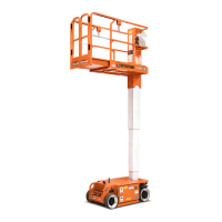
The TM12 consists of the platform, controller, elevating assembly, power module, control mod-
ule, and chassis.
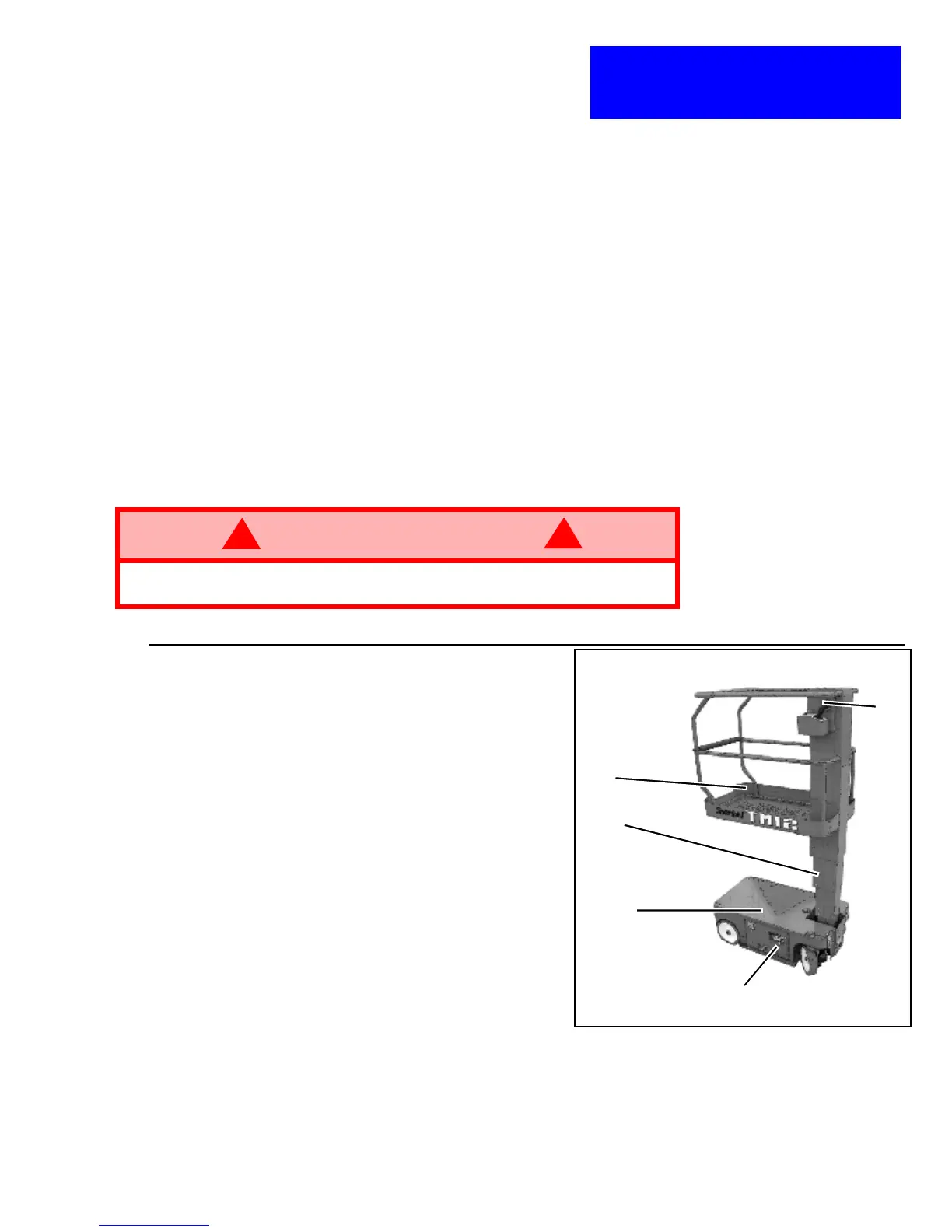
Figure 1-1: TM12 Work Platform
PLATFORM
The platform has a reinforced steel floor, 1.11
m (43.75 inch) high guardrails with midrail, 6
inch (152 mm) toeboards, and an entrance
gate at the rear of the platform.
PLATFORM CONTROLLER
The platform controller contains the controls
to operate the machine. It is located at the
front of the platform. A complete explanation
of control functions can be found in Section 2.
ELEVATING ASSEMBLY
The platform is raised and lowered by the ele-
vating assembly. The hydraulic pump, driven
by an electric motor, powers the cylinder.
Solenoid operated valves control raising and
lowering.
CHASSIS
The chassis is a structural frame that supports all the components of the TM12 work platform.
The platform is raised and lowered using a scissors mechanism. Lift is achieved using a single
stage cylinder.
PURPOSE OF EQUIPMENT
The objective of the work platform is to provide a quickly deployable, self- propelled, variable
height work platform to elevate personnel and materials to overhead work areas.
WARNING
!
!
DO NOT use the work platform without guardrails properly assembled and in
place.
1.Platform
2.Platform Controller
3.Elevating Assembly
4.Chassis Controls
5.Chassis
1
2
3
4
5
 Loading...