Fluid Level Switch
Instructions
• Locate desired level switch mounting position. Suggested
placement is 1/5 of max reservoir height.
• Carefully drill side of reservoir using 13/16” bit. A step bit is
recommended for best drilling results. Hole
must be free of nicks or shavings for proper
sealing.
• Remove rubber seal from level switch.
Insert seal into reservoir until fully seated.
Goop can be used around the edges of the
hole.
• Lubricate exterior of level switch with water
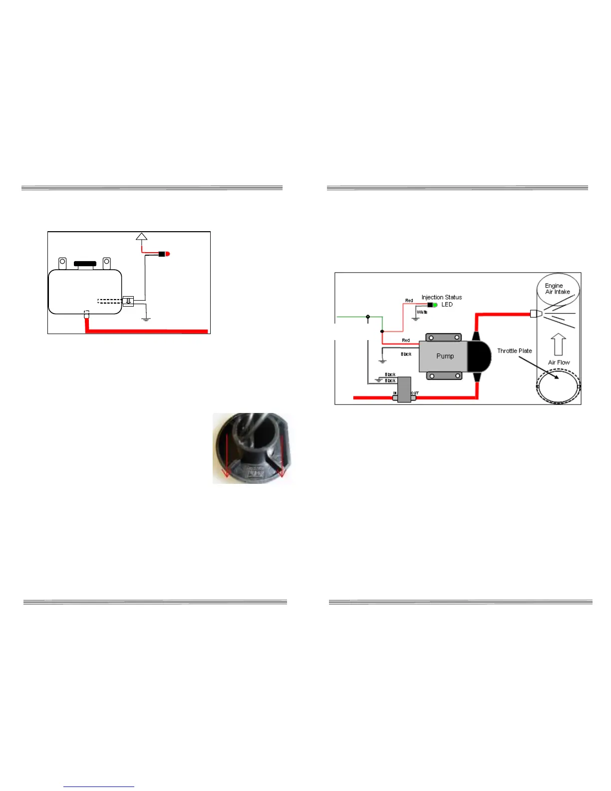
and insert into seal until fully seated. Position level switch so GT
symbol is at six o’clock position.
• Wait 30 minutes for Goop to cure, then test for leaks. With fluid
level above level switch, float should be angled up. With fluid
level below level switch, float should be in horizontal position.
• Connect one black wire from level switch to ground.
• Connect other black wire from level switch to white wire from
LED.
• Connect red wire from LED to +12 volt key on power source.
Low Fluid LED
Black
Solenoid Upgrade (optional)
The optional Solenoid Upgrade (#40060) is required if the nozzle is to be
installed after the intake throttle plate (as shown), or the fluid reservoir is
mounted higher then the nozzle. It is highly recommended for trunk-
mount reservoirs.
Finger thread the two 1/8” NPT quick connect fittings into ports labeled (2
or IN) and (1 or OUT) on the solenoid. Tighten an additional half turn
past finger tight.
Note: Solenoid must be installed Pre-pump to ensure
correct operation.
Cut high pressure line at location solenoid is to be installed. Insert ends
of cut line into quick connect fittings of solenoid. The port labeled (2 or
IN) is the inlet and the port labeled (1 or OUT) is the outlet. Gently pull
on line to check secure connection. If line pulls out, re-insert farther into
fitting to engage locking clips. If high pressure line removal is required,
firmly press in metal fitting ring to disengage locking clips while pulling
hose from fitting.
Connect one of the BLACK wires from solenoid to the RED positive
pump wire or the WHITE wire from the controller. Note that connecting
the wire to any other power source other then the pump/controller wire
will result in improper operation of solenoid. Connect the second BLACK
wire to a secure chassis ground location.
White from S3
 Loading...