Step 5 Nozzle Connection
Measure the distance from the solenoid outlet to the nozzle holder(s).
Cut the ¼” tubing using a sharp utility knife or razor blade. Make cuts as
square as possible.
Ensure there are no kinks in the tubing and insert tubing into quick
disconnects until fully seated. Gently pull on tubing to ensure a good
connection. Also ensure that engine movement will not stress the tubing
or fittings.
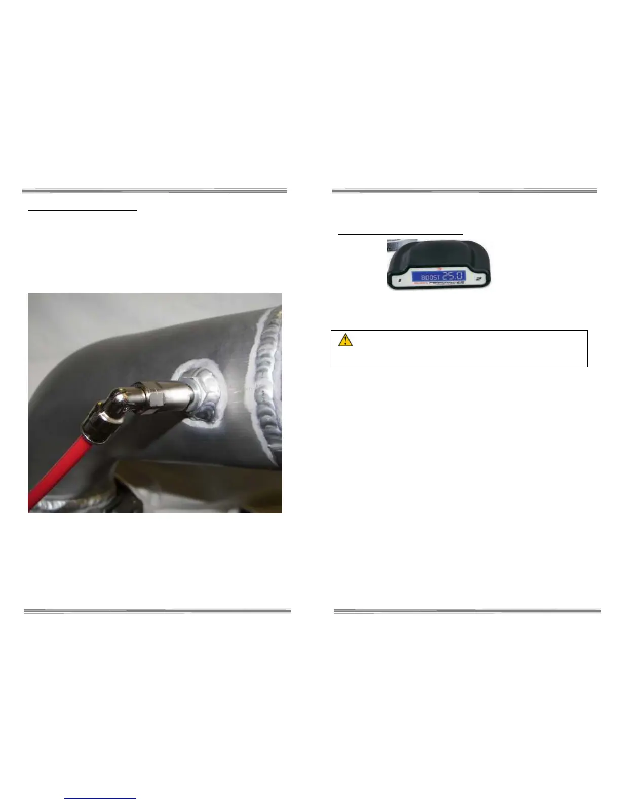
Optional Weld-In Bung Shown
Use tie wraps to help route tubing and to ensure it doesn't contact
moving or hot parts in the engine compartment. Have tubing connect to
quick connect fittings at shallow angles. Having an immediate sharp
bend may unseat the tubing from the internal o-ring and create a leak.
Continual insertion and removal from quick connect fittings will mar the
end of the tubing. Over time the internal gripping teeth may lose their
hold of the tubing which may create a leak. If this occurs simply remove
the tubing and make a fresh cut using a razor blade.
Installation – Electrical
Variable Controller Installation
The Stage 3 controller has an integrated wiring harness for ease of
install and a clean appearance. Refer to the main wiring diagram and
listing below for installation.
CAUTION: Disconnect the negative battery terminal while
connecting wires to prevent electrical fire or damage to controller.
• Connect BLACK wire to a good ground location.
• Tie GREEN wire out of the way.
• Connect RED wire to a 12 volt key on power source. When selecting
a power source look for a dedicated circuit that you can tie into
before the fuse. The controller is internally fused. A good source is
the cigarette lighter.
• Connect the two BLUE wires to the two wires leading to a fuel
injector using the provided wire splices, DO NOT SOLDER THESE
CONNECTIONS. Any injector will suffice, so choose one that is easy
to access. In carbureted applications, these leads can simply tied out
of the way.
• Connect the clear tubing to the black silicone line. This line can be
‘T’ed into any accurate manifold boost pressure source. A boost
gauge line that is tapped into the intake manifold is ideal. In naturally
aspirated applications, this can simply be tied out of the way.
• Connect the WHITE wire to the red power wire of the pump. The
BLACK wire on the pump goes to a good chassis ground.
 Loading...