Caution*******
Whenever the nozzle is mounted post-throttle plate, to avoid siphoning
fluid at idle, it is essential to use a solenoid upgrade inline between the
reservoir and pump.
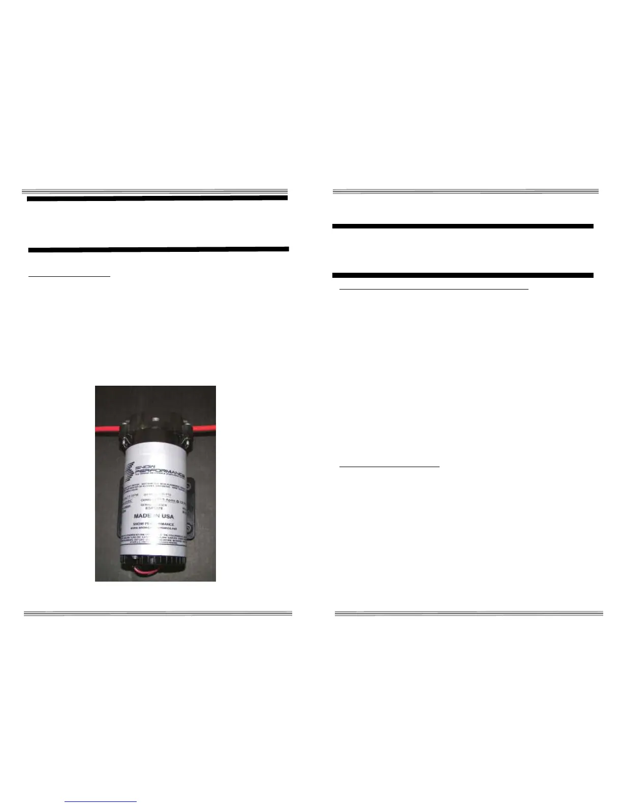
Step 2 Pump Install
Mount the pump so the inlet is positioned at the lowest point of the
reservoir or lower. Pump can be mounted horizontally or vertically using
the supplied screws and washers. Ensure that no sharp bends in the
high pressure tube occur near the pump. Sharp bends can cause stress
on the inlet and outlet ports of the pump, causing leaks. Trim tube with a
utility knife or razor blade, making sure to eliminate any burrs or kinks on
the end. Insert firmly into the pump about ½ inch through the light grey
locking collar. Note the arrows indicating flow direction on the top of the
pump. To remove the hose, gently and evenly push the light grey locking
collar into the head unit of the pump, then pull on the hose gently.
Measure the distance from the reservoir outlet to the pump inlet. Cut the
¼” red tubing using utility knife. Make cuts are as square as possible.
Caution******
Pump must be shielded from road debris and tire wash.
Failure to do so will result in pump failure
Note: for best results, prime pump before use
To clear air from the pump and insure that the system is primed:
• Fill reservoir with water approx ¼ full.
• Remove tubing from nozzle (or solenoid if solenoid used in-line
between pump and nozzle) and run tube into separate container.
• Apply 12 VDC to red pump wire for approximately 5 seconds or
until fluid flow is consistent.
• Pump is now primed. Reconnect tubing from pump outlet to
nozzle (or solenoid).
If using a check valve in between the pump and the reservoir:
Remove the check valve and place a solid piece of tube between the
pump and the reservoir and prime the system. Then replace the check
valve in between the pump and reservoir.
Ensure there are no kinks in the tubing and insert tubing into quick
disconnects at pump and reservoir until fully seated. Keep the pump
within 2 feet of the reservoir.
Step 3 Nozzle Selection
Nozzle sizing is a function of horsepower, which approximates the
engine airflow, and boost, which approximates intake charge heat. The
following are some general guidelines (assuming 50-50 water-methanol).
Engines running mild or high boost and making 400-600 HP will use a
375 ML/MN nozzle or 625 ML/MN nozzle.
Engines making mild boost and 200-400 HP will use a 175 ML/MN
nozzle or a 225 ML/MN nozzle.
A naturally aspirated engine making 200-400 HP will use a 100 ML/MN
nozzle or a 175 ML/MN nozzle.
 Loading...