South Bend, Indiana USA | networketi.com
SNOW/ICE CONTROL INSTALLATION MANUAL | PART NO. 23918 REV B
14
4. With satisfactory results, control and sensor pre-
operational testing is now complete. Disconnect and
remove all testing devices from the system.
5. Once all post-installation testing is complete and with
unit power off, restore all wiring connections.
6. Re-install the face plate and clear plastic cover onto
the control. Set the Hold-On Time control dial to the
desired setting.
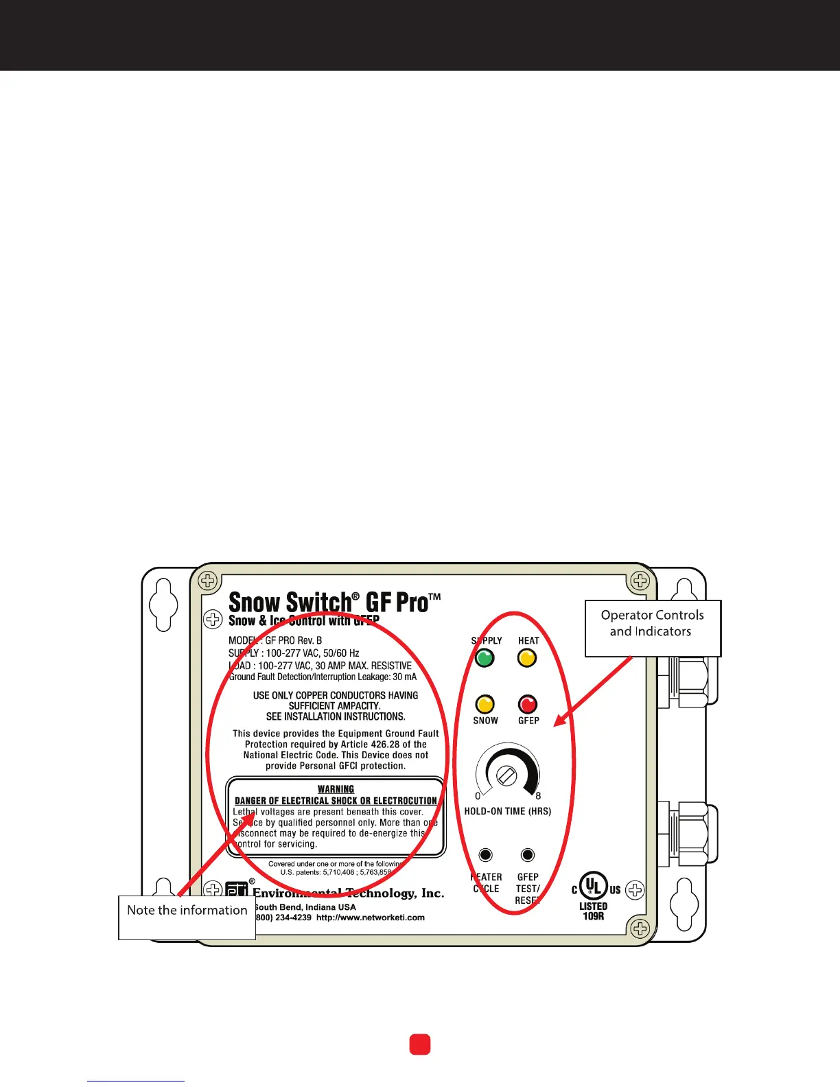
OPERATION
This section presents operating instructions for the unit
and begins with a picture of the front panel. Refer to
Figure 5. Note the system information on the left side of
the panel, as well as the operator controls and indicators
located on the right side of the panel. The controls and
indicators are explained in this section.
Note that because the unit has no ON/OFF power
switch, power runs to the unit as soon as facility power
is connected to it. For as long as power is running to the
unit, the green SUPPLY LED will always be lit. The unit
initiates a heating cycle when the system sensor(s) detect
snow or ice at or below 38°F (3.3°C).
Upon initial Start-Up, all of the LEDs will come on for 2.5
seconds, and then shut off for 2.5 seconds. Following
this, the unit performs a ground fault self-test which lasts
about two seconds, during which the GFEP LED will blink
rapidly, about 8 times per second. During this phase of
the test, the yellow heat tape leads are live. After this, the
device goes into normal operation.
FIGURE 5. The GF PRO Front Panel
NOTE: Cover screws maximum torque: 4 In-Lbs.