South Bend, Indiana USA | networketi.com
SNOW/ICE CONTROL INSTALLATION MANUAL | PART NO. 23918 REV B
9
SYSTEM SCHEMATIC DIAGRAMS
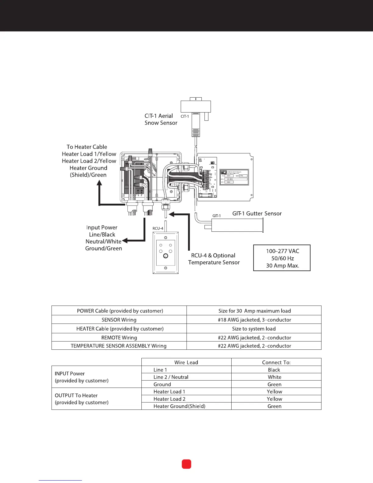
Figure 2 is a schematic diagram of an entire GF Pro system,
including the available optional components.
TABLE 2. Cable Ratings and Connections
FIGURE 2. Representative GF PRO System Schematic