South Bend, Indiana USA | networketi.com
SNOW/ICE CONTROL INSTALLATION MANUAL | PART NO. 23918 REV B
17
OPTIONAL REMOTE CONTROL OPERATION
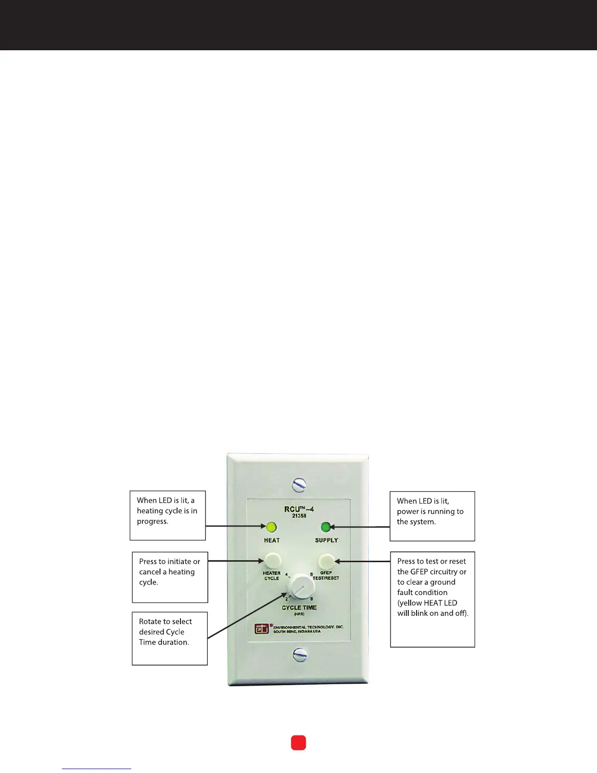
The GF Pro can be operated either “locally” on the face
of the unit itself or by using the optional Remote Control
Unit, RCU–4. Refer to Figure 7.
The RCU Cycle Time control dial moves in discrete
increments rather than in a continuous motion as on the
control box. Cycle Time on the RCU applies only to a
manual heating cycle initiated at the RCU, not the Cycle
Time setting on the control box. The RCU cannot be used
to manually cancel a heating cycle which was manually set
on the control box.
To manually start a heating cycle using the RCU, press
the RCU Heater Cycle control button. The RCU HEAT LED
light will come on. This will start a heating cycle which will
last as long as the RCU Cycle Time setting.
To manually cancel a current heating cycle which was
manually set at the RCU, press the RCU Heater Cycle
button. The RCU HEAT LED light will go out.
To use the RCU to change the duration of a heating
cycle that was manually set on the RCU, turn the RCU
CYCLE TIME control dial to the desired setting, either
higher or lower.
If a ground fault condition occurs, the RCU HEAT LED light
will blink on and off. To test or reset, press the RCU GFEP
Test/Reset button once and release. The GFEP circuitry
will initiate a self-test. During the test of the ground fault
circuitry, the HEAT and SUPPLY LED lights will both ash,
alternating back and forth between them.
If, following the test of the ground fault circuitry, the HEAT
LED still blinks, this indicates the presence of a ground
fault condition which will require repair before system
operations may continue. Refer to Using the GFEP Test/
Reset Button on page 23.
MAINTENANCE
To ensure the best function and results, it is recommended
to always keep the area around the sensors clean from
debris and general obstructions to maximize the ability of
the sensor to do its job. Clean the sensor using a cleansing
pad and water. Keep the gutters clean and the area around
the sensor free of leaves or other debris which could limit
the ability of the sensor to detect the conditions necessary
for optimum system performance. Finally, once monthly,
visually inspect the fuse LED located on the front panel
circuit board to make sure it’s on. If the fuse LED is not on,
change the fuse.
FIGURE 7. Remote Control Unit RCU–4