#56663 SNOW THROWER OPERATOR’S MANUAL 8
ASSEMBLY INSTRUCTIONS
Unpacking
1. Carefully remove your Snow Thrower and all other
items from box.
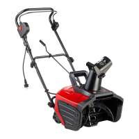
2. Your Snow Thrower comes with the following
accessories.
T-bolt: 4 pieces
Saddle Washer: 4 pieces
Knob: 4 pieces
Cable Clip: 3 pieces
Upper Chute Crank: 1 piece
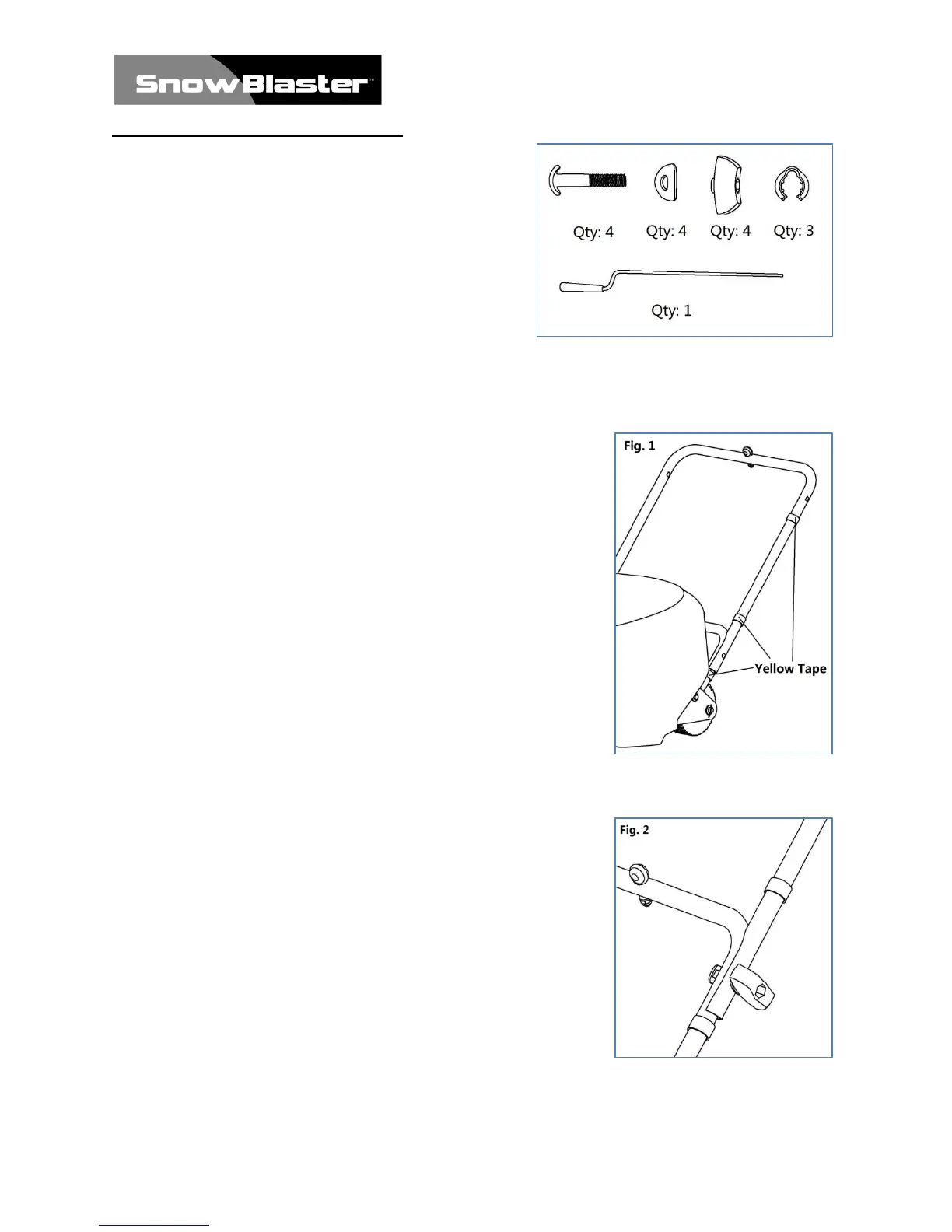
Middle Frame Assembly
For easier assembly, the handle frames are marked with yellow
tape from the factory. This tape indicates the LEFT side of each
handle’s part, as viewed from the operator’s position of the
Snow Thrower.
Hold the Middle Frame with the yellow tape on the LEFT side
so that the screw holes align with the holes on the Lower Frame.
Note also that the hole and grommet of the Eye Bolt at the top of
the Middle Frame are facing UP. (Fig. 1)
Insert a T-bolt into each hole with the head on the inside of the
handle. Then attach a saddle washer and knob on the outside
and tighten. (Fig. 2)
Repeat this step on the other side of the handle.
The bolts should be inserted from the inside of the frame of the
unit so that the washers and knobs are fastened to the outside of
the frame.
Note: Do not over-tighten the knobs.