TROUBLESHOOTING MALFUNCTIONS AND MAINTENANCE
Malfunction checklist
Heater does not start after being turned on; switch the heater OFF and ON again.
If the heater still does not start, check the following:
Is there fuel in the tank ?
Are fuses ok ?
Are electrical cables, all connections, etc OK ?
Is anything clogging the combustion air supply or exhaust system ?
Does the control panel flash the fault code ?
To resets the system press down / OFF, button waiting for 15 minutes, it should clear the fault
codes, turn ON the system. If the system does not clear the code, disconnect battery power,
wait few minutes, hook up the battery power and turn the system ON.
Maintenance Instructions
Switch the heater ON once a month for about 10 minutes, even if there is no need for heat.
Check the opening of the combustion air supply and the exhaust system after longer standstill
periods; clean if necessary.
Before the heating period starts the heater should undergo a trial run. If persistent extreme
smoke, unusual burning noises, or an unburned fuel smell develop or if electric /electronic parts
heats up, the heater shall be switched OFF immediately. Remove fuse or disconnect battery
power.
Have the heater checked by authorized, trained service technician.
At least once a year have the heater checked by authorized, trained service technician.
Remove glow pin and atomizer; clean the screen and the atomizer chamber with wire brush, if
notice that there is excessive carbon build up the entire combustion chamber shall be cleaned
out.
Please note:
The warranty claims will become void if the heater is repaired or serviced by an
unauthorized person.
Water heater fault code
SNUGGER
14
SNUGGER
13
SS5000 WATER HEATER
SNUGGER
Code flashing
times
1 Time
Description
Solution
Check the voltage, possible alternator drive belt
too loose, check charging system
Check the voltage, charge battery, check charging
system
Check the temperature sensor connection and
position whether it is correct
Check the temperature sensor wires for possible
damage or short
Check the voltage between glow pin terminals it
should read 12 or 24 V
Check for broken wires and loose connection,
short out wires
Remove and check the glow pin for any visible
damage; replace glow pin if damaged
Check voltage at fuel pump it should pulsing 12V / 24V
Check wires for damage, check connections and
shorted circuits
Check fuel pump for any damage
Check blower wires for damage and proper
connections
Check blower for any visible damage
Check wiring connections
Check water pump for debris
Check for cramped/collapsed hoses
Check if there is fuel in tank
Check all fuel line connections
Check fuel pump if it is working
Check the glow pin if it is working normally
Check the air inlet/exhaust if it’s not blocked
Check the fuel pump pressure
Defective fuel injector
Check water flow
Check overheat sensor
3 Times
4 Times
5 Times
2 Times
The power supply voltage too high
Burner overheating protection
Lgnite failed or flame extinguish
protection
Water pump malfunction
Blower malfunction
Fuel pump malfunction
Glow pin malfunction
The power supply voltage too low
The burner temperature abnormal
Inlet water temperature sensor
abnormal
Outlet water temperature sensor
abnormal
6 Times
7 Times
8 Times
9 Times
10 Times
11 Times
Check water level
Bleed water system
Check water flow
Check warm water temp, Sensor
Outlet warm water temperature
overheating protection
12 Times
Check fuel pressure
Check overheat temp, sensor
Check water flow
Disconnection power and re-connection again
13 Times
Flame extinguished or burner
overheating forbids the system
operation
14 Times
Communication fault Check all wire connection.
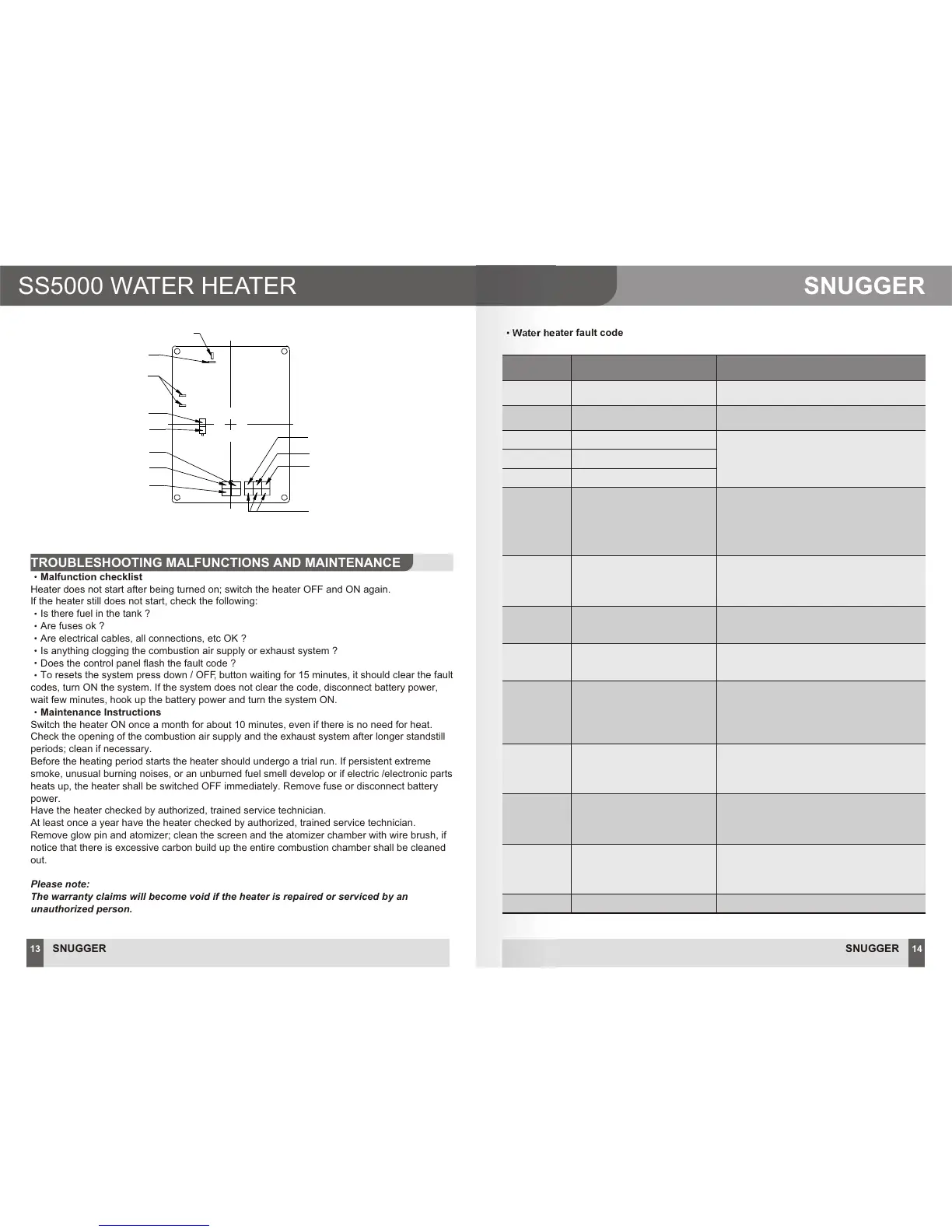
Flame temperature sensor
Outlet water temperature
Inlet water temperature
Sensor common terminal
2 ECU Wiring Diagram
Combustion motor (-)
Combustion motor (+)
Glow pin
Water pump output (+)
Water pump output (-)
Speed sensor output (-) (black)
Speed sensor output (+) (red)
Speed sensor signal (yellow)