OPERATING INSTRUCTIONS
DESCRIPTION OF FUNCTIONS
CONTROLS AND SAFETY DEVICE
Before starting the heater, perform a safety check: all components must be firmly fastened,
check for fuel leaks, make sure the heater is filled with water or coolant (all air shall be bleed
out). Bleed fuel line and prime fuel pump.
To start the heater; turn the thermostat to high (turn the knob clockwise), push heat bottom, the
blower motor will start running. After about 45 sec. the fuel pump will start pumping. If the fuel
is not ignited in about 90 sec. (possible air in fuel line) the glow pin will shut down for about 1
min. and then it will start the process again. The process will repeat until there is no more air in
fuel line.
Heater at high altitudes:
1. Heating at altitudes below 5,000" (1,500m), -unlimited heating possible.
2. Using heater at altitudes higher than 5,000" (1,500m) requires installing an altitude pressure
fuel pump.
Operation (when vehicle parking)
When the heater is turned ON, the control lamp comes ON. Water pump start pumping,
combustion air blower starts running, glow pin starts heating up and fuel pump starts pumping
fuel. Once the flame is stable, glow pin will turn off.
Heating mode
According to the demand of heating, heater have three level, high-low-shut down.
Once the water reaches 175 (85¨H) the heat will turn OFF, the combustion fan and water
pump will continue to operate on the low speed. The heat light will stay ON. The heater will
restart after water temperature drop below setting point. After the heater is turned OFF the
exhaust fan and water pump will run for approximate. 2 min. In order to evacuate exhaust
fumes and cool off the combustion chamber.
If the heater does not ignite within 90 seconds after starting the fuel pump, the process repeats
several times. After several unsuccessful starting attempts the controller will lock the system in
order to prevent fuel flooding the chamber. You can restart the process by switching the heater
OFF and then ON.
If the flame goes off during operation, the heater will restart by itself. If the heater does not
ignite after several attempts, the heater will lock and it will need to be turned OFF and ON
manually.
In the case of overheating (for example, lack of water, poorly vented coolant circuit), the
overheating sensor is triggered, the fuel supply is interrupted and the heater turns OFF. Once
the overheating has been eliminated, the heater can be restarted manually by turning OFF and
ON again. The heater will turn ON when the water temperature drops below 158 (70¨H). If
the heater has been switched OFF and ON too many times, the controller will lock, wait for
about 15 min. and turn the heater ON again.
If the lower or upper voltage limit is reached, the heater will turn OFF.
The heater does not start when the glow pin is defective or when the fuel pump power is
interrupted.
The fan speed is continuously monitored. If the fan motor does not start or if the speed drop to
less than 40%, the heater will turn OFF after 60 sec.
The controller can be enabled again and it will flash fault code:
Use chart below to read the fault code list.
Do not switch the heater OFF and ON again more than twice.
Please note:
Emergency shut down.
In event of an emergency, shut down the heater as follows:
Try to turn the heater OFF with the control panel.
Pull the fuse out.
Disconnect battery power.
Safety Instruction for wiring the heater
The Heater shall be connected to the power according to the EMC requirements. See
instruction below.
Ensure that the electric cable’s insulation is not damaged. Avoid: chafing, kinking, jamming or
exposure to heat.
Seal all unused connector chambers with filler plugs to ensure there are not dirt enter into and
water-proof.
All electrical connection shall be free of corrosion and firmly connected.
Lubricate all outside connections with contact grease.
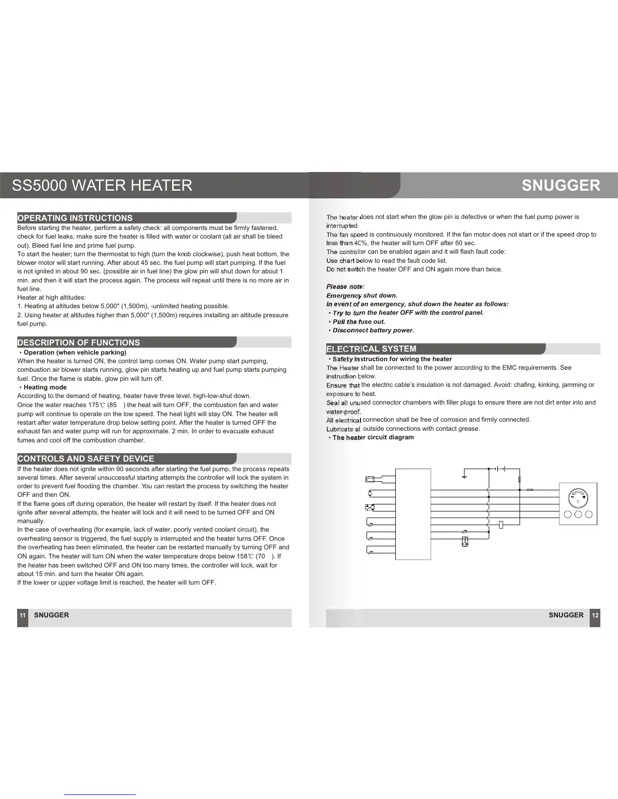
The heater circuit diagram
ELECTRICAL SYSTEM
SNUGGER
12
SNUGGER
11
SS5000 WATER HEATER
SNUGGER
SI/N
M
OFF
HEAT FAN
Glow pin
Combusition motor
Water pump
Flame
temperature senor
Outlet water
temperature senor
Inlet water
temperature senor
M
Dose pump
SW 0.75
VI 0.75
BL 0.75
GN 0.75
GE 0.75
OR 0.75
BR 0.75
SW 1.5
RT 1.5
ECU
GND
SW 4.0 B RT 4.0
FU 1
FU 2
RT 4.0
SW 4.0
K
1.Control Principle Diagram