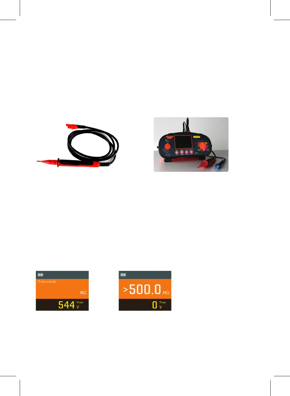
Test Procedure
Insert the brown test lead into the brown input terminal & the blue test lead into the
green terminal.
When test is activated the red Voltage/Polarity will flash warning there is voltage on the
leads and circuit under Test.
Select insulation on the rotary switch either 250V, 500V, 1000V setting as required.
Connect the brown test lead to the phase conductor and the blue test lead to the other
conductor under test and press the test button.
Press the test button, the tester will beep indicating voltage output through the test
leads and the circuit under test. The display will indicate output voltage then display
the result of test in MΩ. 0V output will indicate if finished and voltage present.
Example Screens
The brown test lead can be substituted by using the red remote test probe supplied. This
allows remote activation of the MFT5000 from the safety of the test probe ensuring that
you are always looking at the point of contact and not the MFT5000.
12