Insulation
Caution
Measurements shall only be carried out on de-energized circuits.
If the tester is connected to a live circuit (25V or greater), the LED will flash red and the
hazard buzzer will sound. Your Socket & See MFT5000 is fully protected but measured
RMS voltage will be displayed on the secondary/lower display. Further testing after this
point will be inhibited. To resume testing, disconnect the test leads and isolate the
circuit.
All equipment and appliances should be disconnected from the circuit under test.
Attached equipment may be damaged by the higher voltages applied during testing and
may return an artificially low test result.
There may be capacitance on the circuit being tested. Your tester will automatically
discharge this but do not disconnect the test leads or change tester function until
auto-discharge has completed.
Warning
Do not touch the ends of the test leads while on the Insulation test functions as they are
energised.
Results of measurements can be adversely aected by impedances of additional
operating circuits connected in parallel or by transient currents.
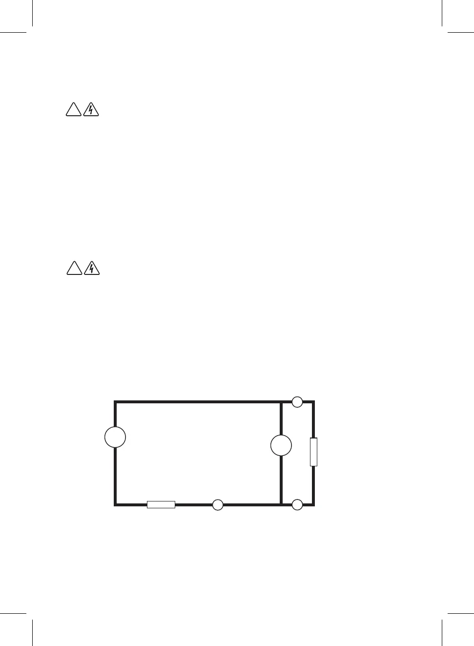
Principle of Measurement
During insulation measurement the tester generates a high voltage internally. The positive
side of this is connected to Brown (VΩ) lead causing a very small current to flow through
the external insulation resistance, Green (COM) lead, meter resistance and finally back to
the negative side of the HV generator.
The current and voltage are measured as shown and the external resistance calculated and
displayed.
!
!
RE
GREEN (COM)METER RESISTANCE
BROWN VΩ
v
HV
A
11