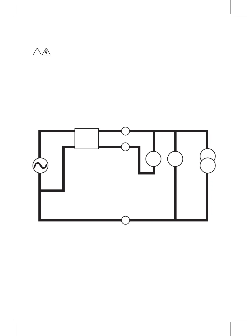
BROWN (L)
BLUE (N)
GREEN (PE)
v2v1
RCD
RCD
Warning
Leakage currents in the circuit following the residual current protection device may
influence the measurements.
Potential fields of other earthing installations may influence the measurement.
Special conditions in S-type residual current protective devices shall be taken into
consideration.
Equipment connected downstream of a residual current protective device (RCD) may
cause considerable extension of the operating time. Examples of such equipment might
be connected capacitors or running motors.
Principle of Measurement – x1/2, x1, x5
During normal RCD test an earth leakage current I is applied to unbalance the RCD.
During application of the current, VLN is monitored using voltmeter V1 for an RCD trip
signature. When trip occurs, the time from application of the earth leakage current to
the trip is calculated and displayed.
Additionally, VLE is measured using voltmeter V2 to monitor Fault Voltage. If excessive
Fault Voltage is detected, testing is aborted and a warning is displayed. This detection
uses the actual Fault Voltage occurring during the test and not the predicted fault
voltage at the rated residual current.
Application of the current is limited in duration. If no trip is detected during the
application, an over range reading is displayed. Note: when testing at x1/2, no trip is a
PASS.
!
24