88
Configuring connected devices
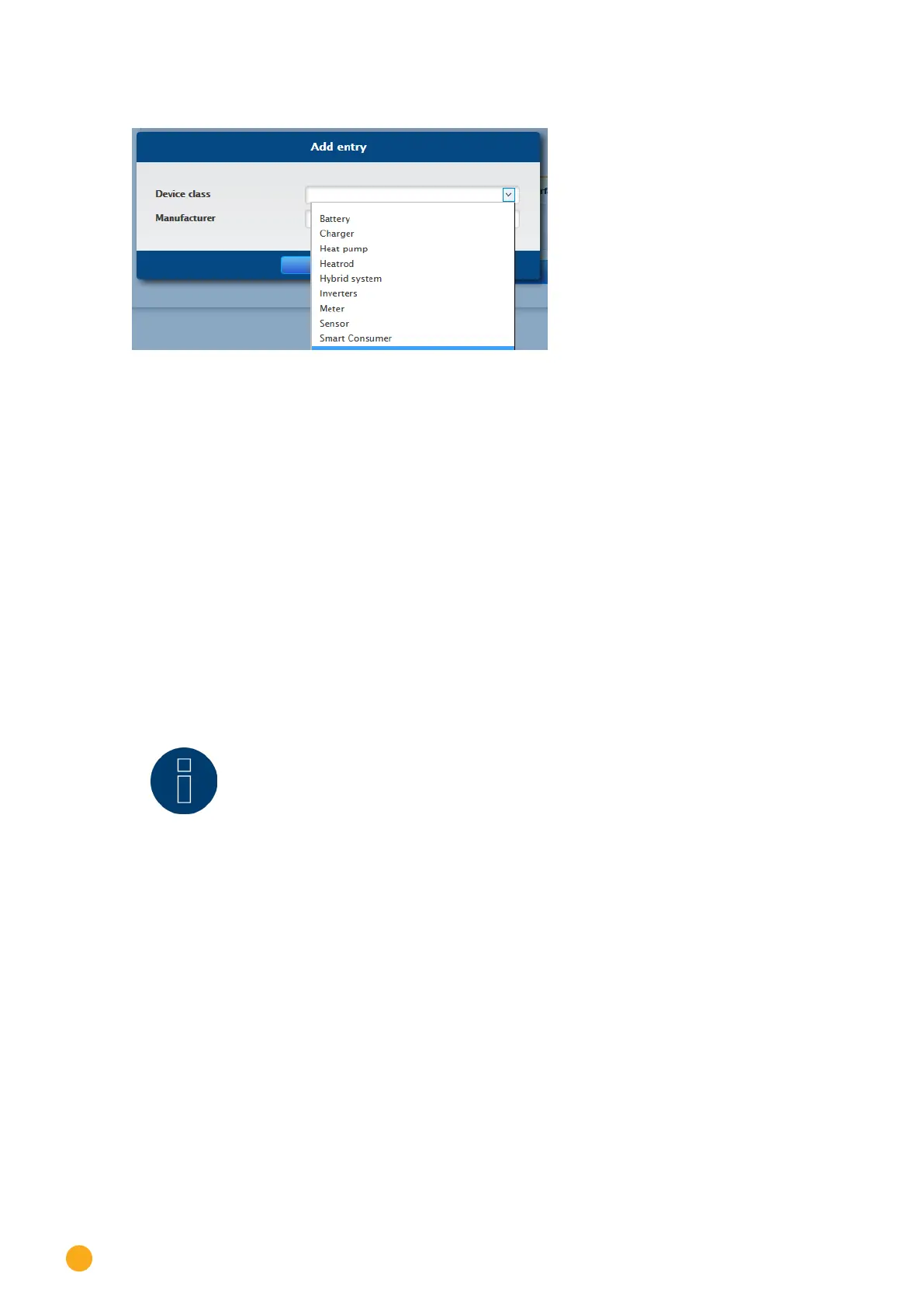
The following window appears:
Fig.: Adding components
The connected components are selected in the Device class box. The following device classes can be
defined:
•
Battery
•
Hybrid System
•
Smart Appliances
•
Switch
•
Sensor
•
Inverter
•
Meter
Depending on the device class and/or the selected Manufacturer, additional boxes visible:
Type, Interface and Baud rate.
Furthermore, an existing Wireless Package can be activated here and the expected reply time for a de-
vice connected to this bus is increased.
Note!
Caution: Using different manufacturers on the same serial bus may cause communication
problems.
Only the network interface (Ethernet) can have multiple assignments according to our
component database at www.solar-log.com.
If the device class is correct, confirm the selection with OK. Define additional connected device classes as
described.
If all of the connected components have been selected and confirmed with OK, an overview is displayed in
the interface assignments. (See illustration: "Overview of the selected components")

 Loading...