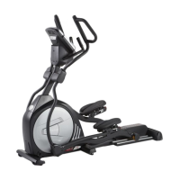
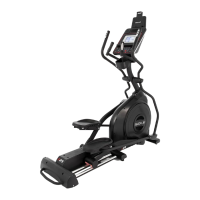
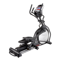
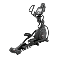
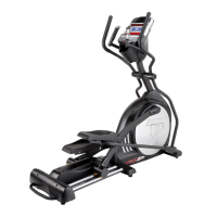
Sole Fitness E95 Ellipcal Trainer
TurnKey® Delivery and Setup Training
Delivery Requirements
• Ground delivery
• Inside delivery to customer-specified locaon
• Unpack and assemble machine, and remove packing materials
Tools Required
• Ligate
• Two-wheel dolly
• Cuers to cut plasc banding
1. Unload the carton from the trailer and take it to the
customer-specified locaon using a two-wheeled dolly.
When moving the carton, be sure to use safe liing
procedures. Be sure to bend at the knees and keep your
back straight.
2. Unpack the contents of the cartons and remove
all
packing
materials.
Cut along the
boom edge
of the carton.
Remove all
packing material.
Locate the
hardware
packet.
3. Review the assembly instrucons.
Inside the carton, you will find the Owner’s Manual. It will be necessary for you to follow the manufacturer’s assembly instrucons to
be able to complete the assembly of the Sole Fitness E95 Ellipcal Trainer.
Do not aempt to assemble this machine without the Owner’s Manual.
4. Install the incline rail assembly into the U-channel bracket of the main frame.
Place the incline rail
assembly into the U-channel
on the main frame.
Install four bolts, split
washers, and star
washers into the top of
rail assembly.
Install two bolts
and two nylon nuts
into the sides of
the U-channel.
Connect the three incline motor power lines and
the 3-pin posion sensor connector on the main
frame to the corresponding ones on the incline
rail assembly.
(This is shown in Step 1.1 and 1.2 on page 8 of the Owners Manual)
Be careful not to pinch or cut the wires.
5. Aach the console mast and console mast cover to the main frame.
Slide console mast
cover onto the
mast.
Pull the cable out
of the top of the
main frame and
unravel and
straighten out.
Feed the cable into
the boom of the
console mast and
out the top.
Install the mast into
the receiving
bracket on the
main frame.
Install one long
hex bolt and split
washer into the
side of the bracket
and mast.
Install two short hex
head bolts and curved
washers into the front
of the console mast.
(This is shown in Step 1.2 and 1.3on page 8 in the Owner’s Manual.)
6. Aach the console to the console mounng plate.
Place the console next to the console mast plate, and then plug all of
the connectors into the back of the console.
Secure the console to the console mounng plate with four Phillips
head screws.
Be careful not to pinch or cut the wires.
(This is shown in Step 1.4 on page 8 in the Owner’s Manual.)
Note: Some deliveries
will require setup in an
upstairs room or other
location with limited
access. When this is
the case, it is recom-
mended that you
unpack the parts
outside and carry
them individually to
the customer-specied
location.