ional standard to control the system. This mode
he XLR connector on the rear of the
ck Reference Char".
s reset, and then the unit begins working.
5. Use DMX console to control your units.
T
he LED light only accepts the DMX51 ight.
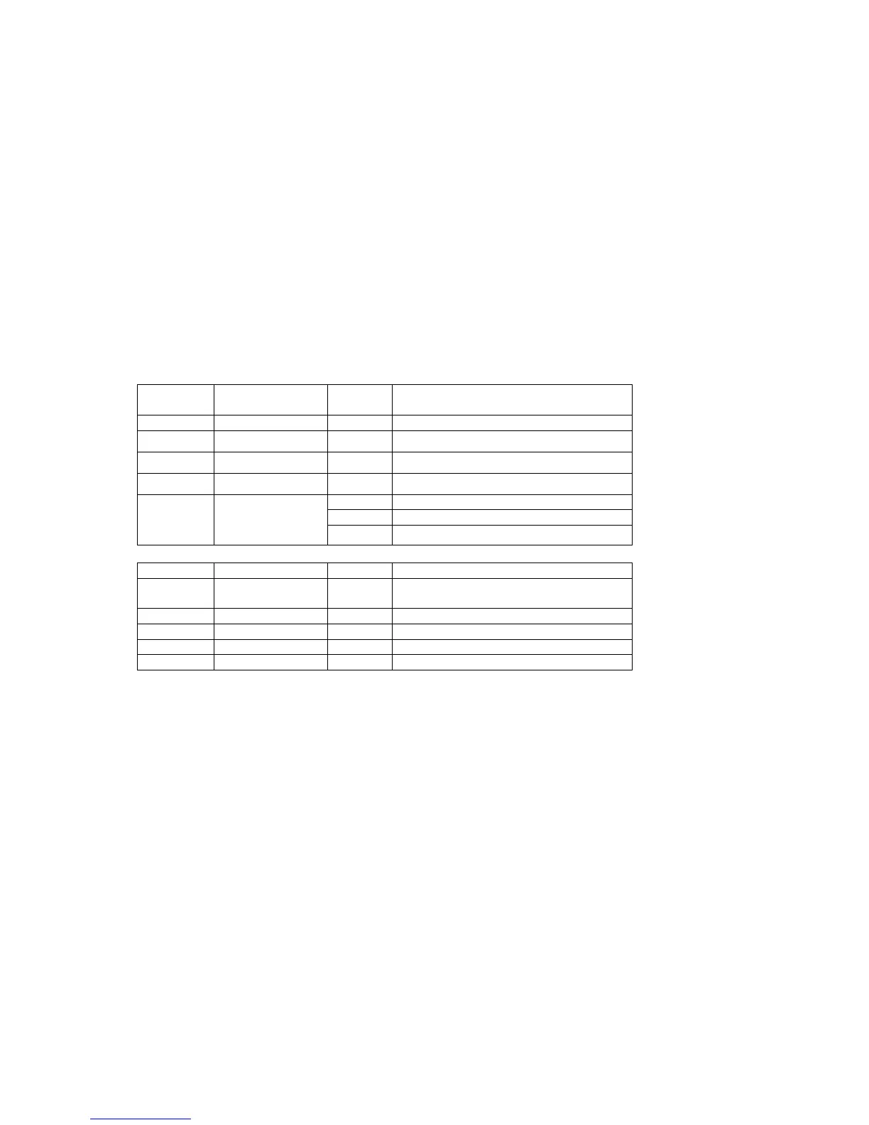
DMX Control Parameter Chart
(1)
Channel Function
Va lu e
Description
Universal DMX Operation (DMX mode)
T
he system only accepts the DMX512 signal of internat
allows you to use universal DMX-512 console to operate.
1. Install the units in a suitable position (laying or appending).
2. Use standard XLR microphone cable chain your units together via t
units. For longer cable runs we suggest a terminator at the last fixture.
3. Assign a DMX address to each the unit using dipswitches, see the "DMX Address Qui
4. Turn on the all units' power, the units begin
DMX Control:
2 signal of international standard to control the l
5 channels
CH1 Red brightness 0-255 Dark to bright
CH2 Green brightness 0-255 Dark to bright
CH3 Blue brightness 0-255 Dark to bright
CH4 White brightness 0-255 Dark to bright
0-63 No strobe
64-223 AUTO strobe, speed from slow to fast
CH5 Strobe/Flashing
224-255 Sound strobe
(2)
nel n tion
8 channels
Chan Functio
Va lu e
Descrip
CH1 All 0-255 Dark to bright LEDs
brightness
CH2 Red brightness 0-255 Dark to bright
CH3 Green brightness 0-255 Dark to bright
CH4 Blue brightness 0-255 Dark to bright
CH5 White brightness 0-255 Dark to bright
Page 6