02/16/98
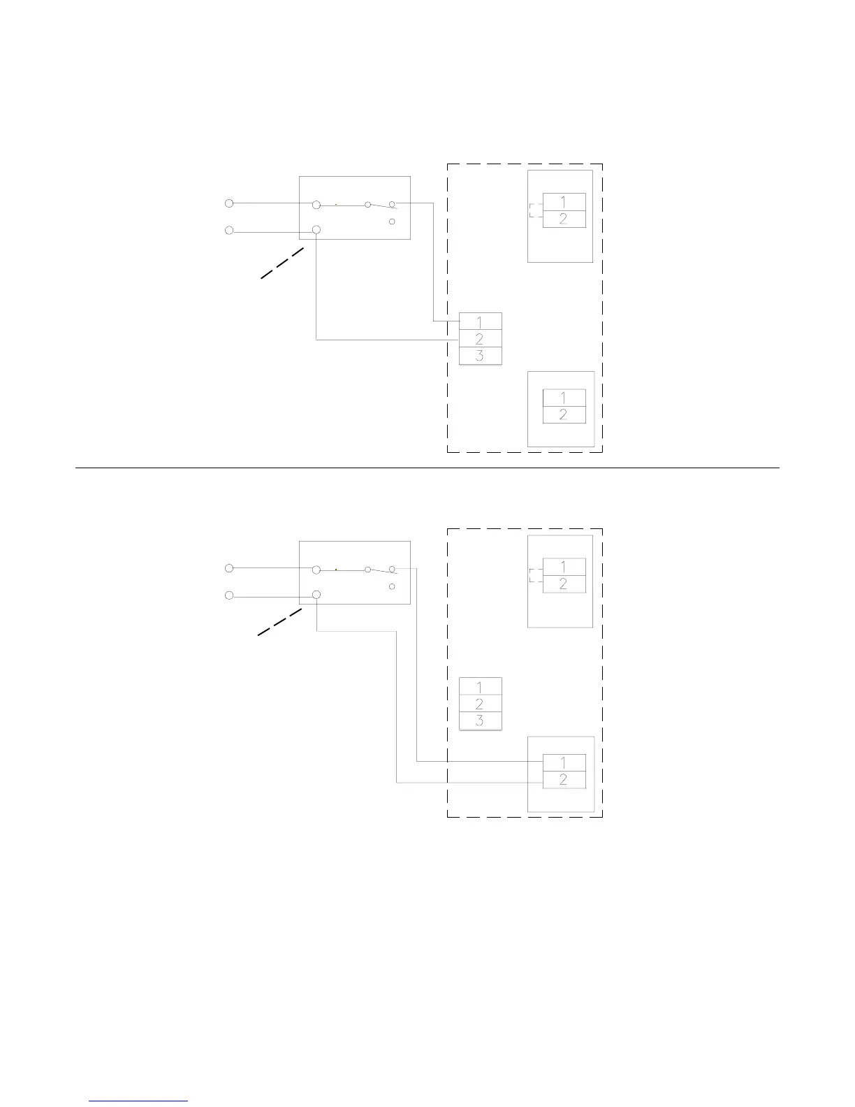
FIGURE 4A - TWO WIRE/SINGLE DELAY
High voltage connections
Model A/B
PC MOUNT
WPS Board
PC MOUNT
WPS PC MOUNT
NOT USED
Initiating Device (Smoke detector, etc.)
24VAC or DC
Input power
(1)
(2)
(3)
(+)
(-)
24VAC/DC ONLY
Observe polarity on
DC units
CHASSIS MOUNT
NOT USED
120VAC
Input power
(1) See NFPA 80 and NFPA 92-1993 for proper placement.
(2) Verify input voltage to model being used.
(3) See smoke detector installation instructions for contact ratings. Installation of all wiring and related connecting hardware must be performed
in accordance with the latest NFPA, U.L., and N.E.C. standards and codes. In addition, all installations subject to Canadian standards shall be
performed in accordance with the Canadian Electrical Code, Part I, with respect to wiring material type, wiring gauge related to power capacity
requirements and circuit length and wiring methods.
(4) Jumper must remain installed for two wire installation.
(5) All fuses 2AG Fast Acting. See page 5, figures 5 &5A for proper ratings
3B
(4)
Model A/B
PC MOUNT
(4)
(1)
(2)
(3)
Initiating Device (Smoke detector, etc.)
TB3
CHASSIS MOUNT
Break wire for
proper supervision.
Do not loop wire
around terminals
Break wire for
proper supervision.
Do not loop wire
around terminals
Low voltage connections