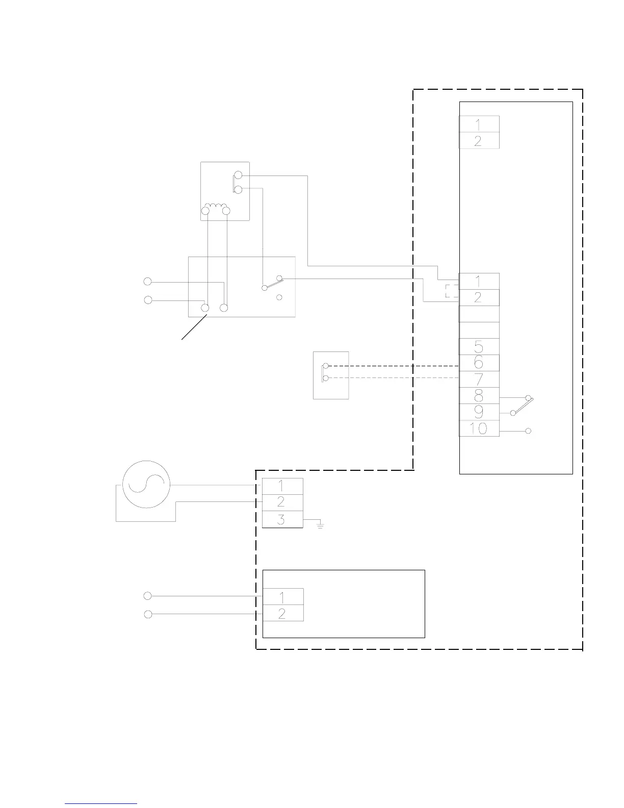
Break wire for proper
supervision. Do not loop
wire around terminals
End of line relay (4)(8)
Per U.L. 864
(2) Initiating Device
(Smoke detector, etc.)
WPS PC Board
24VAC/DC ONLY
Observe polarity
for DC supply
(+)
(-)
Chassis ground
Proximity switch
option Model B
only
Model A/B
PC MOUNT
TB1
(1)(4)(6)
}
Model B Only
PC MOUNT
TB2 Motor sense
TROUBLE RELAY
Model B Only
(unit de-energized)
(1) Dotted line indicates factory jumper which must be removed when connecting the N/C device.
(2) See NFPA 80 and NFPA 92-1993 for proper placement.
(3) Verify input voltage to model being used.
(4) Maximum loop resistance 100 ohms. Verify contact rating of End of Line Relay.
(5) Jumper must remain installed for two wire installation (figure 4A).
(6) Jumper must remain installed if not using this option.
(7) All fuses 2AG Fast Acting. See page 5, figures 5 &5A for proper ratings
(8) End of line relay as per U.L. 864 See smoke detector installation instructions for proper End of Line Relay p/n and contact ratings.
Installation of all wiring and related connecting hardware must be performed in accordance with the latest NFPA, U.L., and N.E.C. standards and codes. In
addition, all installations subject to Canadian standards shall be performed in accordance with the Canadian Electrical Code, Part I, with respect to wiring material
type, wiring gauge related to power capacity requirements and circuit length and
wiring methods.
3A
ELECTRICAL CONNECTIONS (TYPICAL) - FIGURE 4
FOUR WIRE- INDEPENDENT ALARM & POWER LOSS DELAYS
02/16/98
Refer to Section C - Electrical Connections pages 2&3 for complete SS90 wiring instructions. Reference all footnotes below for additional installation
information.
(3) Input power
Down Limit Detection
(1)(4)(6)
(4)(5)(8)
TB3
CHASSIS MOUNT
120VAC only
USE TB3 CHASSIS
MOUNT
120Vac only
OR
low voltage to WPS
PC Board