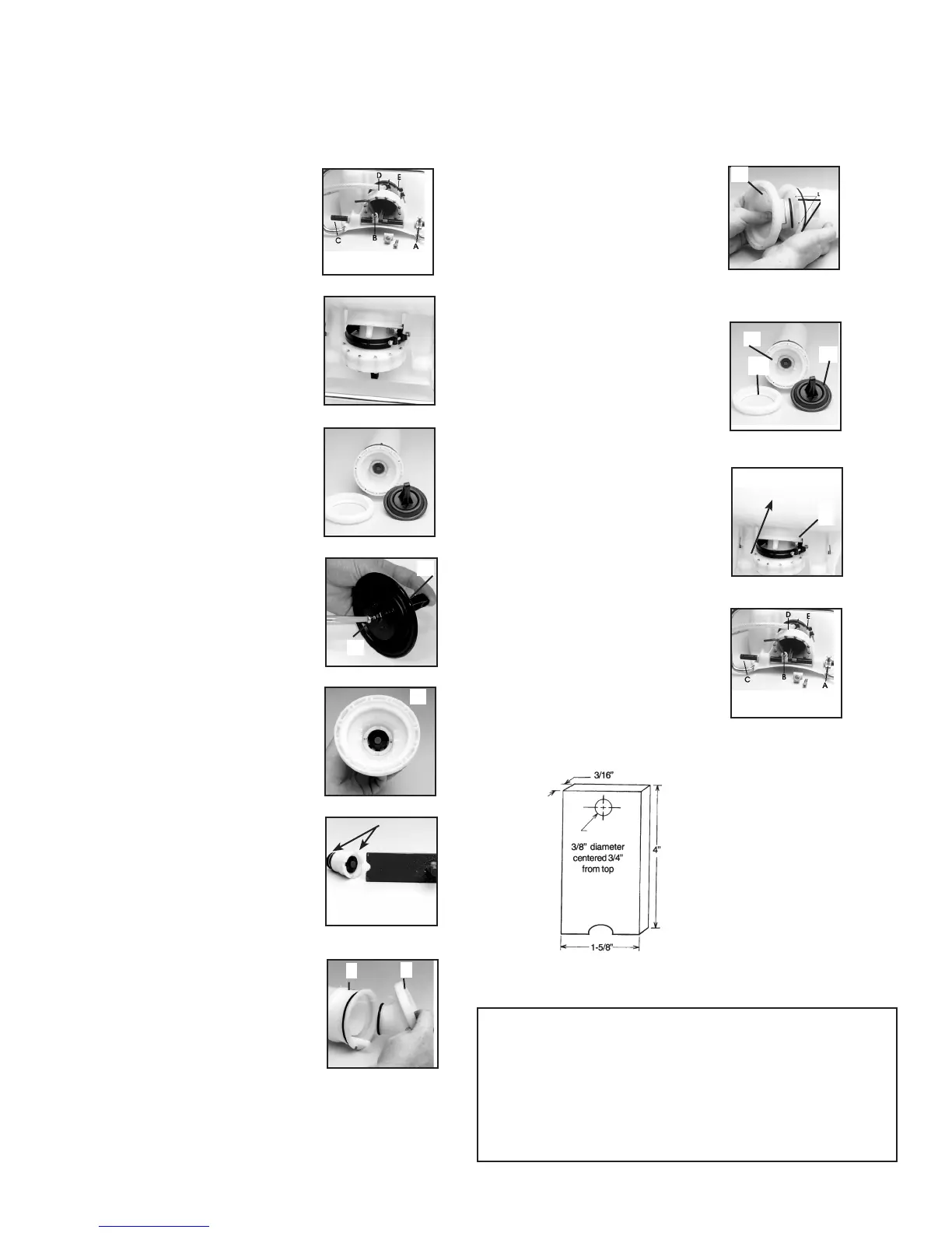
Diaphragm Pump Repair Kit ( # 0610406-K)
1. Using a 13mm socket wrench,
remove handle bolts and loosen the
stop plate (A) and remove the two
allen head screws (B) that hold the
connecting pieces to the pump rod.
Figure 1.
2. With unit laying on its back with
pump assembly facing you, remove
the pump rod (C). Loosen hose
clamp and remove pressure hose
(D). Next, loosen the clamp at the
base of the sprayer (E). Figure 2.
3. Push the pressure cylinder
approximately 1" out of the bottom
of the tank. Then turn the pump
assy. 180 degrees. Note: Wooden
block may be used to tap the pump
assembly through bottom of tank.
Remove pressure regulating valve,
if equipped before removal of
cylinder.
4. Next remove the 12 torx screws
that hold the flange in place. The
flange and diaphragm can then
be removed. Figure 3. Note: For
clarity the pressure cylinder is
shown removed from the tank.
5. To replace the diaphragm,
remove the connecting rod retaining
screw (G) from the plunger and
lever (F). Replace the diaphragm
and reassemble. See Figure 4.
6. The valve assy. (H) is removed
using a locally made tool. Remove
red valve plate retaining pin using
needle nose pliers, then insert tool
into slots. See Figure 5. Use a
screwdriver to rotate tool counter
clockwise.
7. Once the valve assembly is
removed, the valve plates and
O-rings can be replaced. The
bottom valve plate is secured into
place with a red retaining pin. Push
pin into place using needle nose
pliers. Figure 6.
8. The pump housing (I) is
separated from the pressure
cylinder (J) by pulling it off.
Figure 7. The O-ring can then be
replaced.
Figure 6.
Figure 7.
Figure 5.
Figure 4.
Figure 3.
Figure 1.
Figure 8.
Figure 9.
Figure 10.
Figure 11.
Figure 2.
L
M
N
P
O
K
G
F
H
I
J
9. When reassembling the pump
housing to the pressure cylinder, be
sure the square tab on the pump
housing (K) is aligned in the notch.
See arrows (L) on the pressure
cylinder in Figure 8. Be careful not to
pinch or nick the O-ring.
Note: Grease O-rings for re-assembly.
Screw the valve assembly into the
cylinder.
10. Place diaphragm assembly (O)
onto the pump housing (M). Place
the flange (N) over the diaphragm.
Reinstall the 12 torx screws around
the outside diameter of the flange.
Figure 9.
11. Push pressure cylinder into the
tank being careful not to pinch the
large O-ring (P).
Note: Wooden block may also be
used for installation of the pressure
cylinder.
12. Tighten pump clamp securely
(E). Install pump rod (C). Reinstall
the connecting pieces and allen
head screws (B). Reinstall the stop
plate (A) making sure that the bolt
goes through the rear hole. Reinstall
the hose and hose clamp making
sure it is firmly secured (D).
INSTALLATION INSTRUCTIONS
9
Note: Always wear rubber gloves, safety goggles and
appropriate protective clothing when repairing a sprayer. Work
in a well ventilated area. Prior to repair, flush unit with water by
filling, then spraying the water into an appropriate container or
area. Ensure that all pressure is released by locking the shut-off
valve in the open position. Once a repair is completed, fill the
unit with clean water, pressurize, and check for leaks. If the
sprayer leaks, DO NOT USE. Repair leaks and recheck.
Tools needed for kit installation: 6mm Allen Head Wrench, Flat Screwdriver, 11mm Wrench or Cresent Wrench, Long Nose Pli-
ers, Hammer, 13mm Socket or Wrench, T-25 Torx Screwdriver, Grease or Petroleum Jelly, 2X4 Piece of wood 18” long