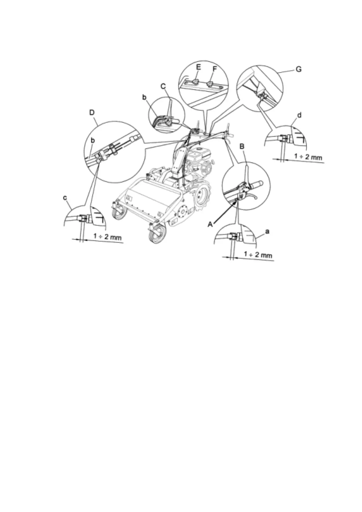
Fig. 5
B1) RIGHT AND LEFT WHEEL RELEASE CABLES ( FIG. 5 REF. A)
Inspect or move the cable sheathing slightly to ensure play of 1-2 mm between the
upper part of the cable and the adjustment screw (Fig. 5,. ref. A, point a). If there
is none, restore to ideal position using the relative adjustment screw. The above
drawing shows the cable of the left lever. Of course, the same operation should
also be performed for the right wheel release lever.