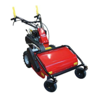
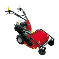
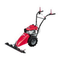
Fig. 7
C1) ROTOR BRAKE
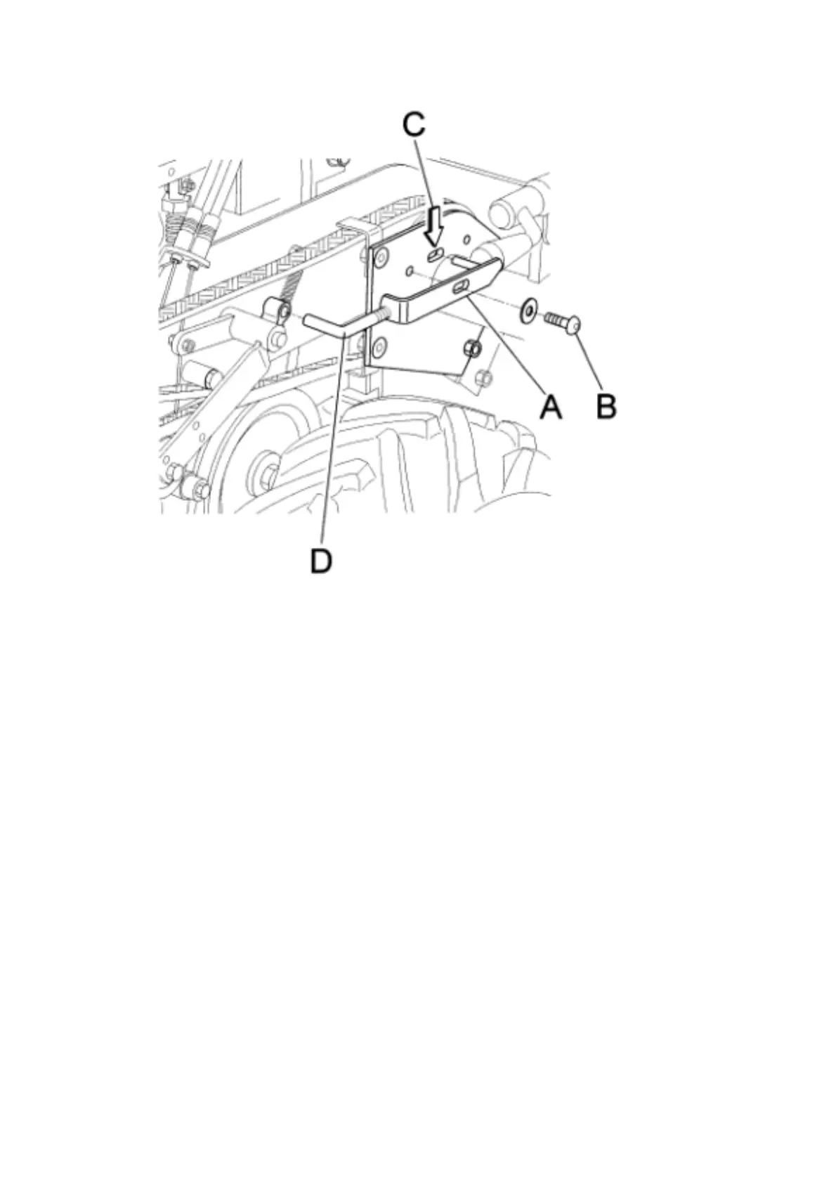
Loosen and remove the screw ( ref. B fig. 7)
Remove the brake adjustment device ( ref. A fig. 7)
Shorten or lengthen the threaded pin as necessary (ref. D fig. 7) by turning clock-
wise or anti-clockwise. Refit the brake adjustment device ( ref. A fig. 7) in its seat
and make sure that the flail rotor control lever performs its safety function cor-
rectly.
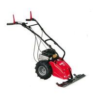
B3) F
ORWARD BRAKE
If upon release of the forward control lever, the machine does not stop immedi-
ately, the brake needs adjusting.
If this is not successful using the relative adjustment screw, to allow play of ap-
proximately 1-2 mm between the wire and its adjustment screw, proceed as fol-
lows : - remove the cover (fig.8 ref. A),
-tighten both springs to the same load (fig. 8, ref. B) using the relative dowels (fig.
8, ref. C)
-check that the brake works properly. If the brake still does not work properly, the
brake lining may be worn, in which case the shims ( fig. 8, ref. D) must be re-
moved so that the eccentric control pin (fig. 8, ref. E) is slightly loose and not
locked into position.
 Loading...