- To access the transmission belts and rotor brake adjustment device area, re-
move the plastic guard (fig. 9 ref. D) and unscrew and remove the 4 screws
shown in figure 9 ref.A.
D2) F
ORWARD BELT
Remove the brake adjustment device (Fig.7 Ref. A) by unscrewing the screw (Fig.
7 Ref. B) and slipping off the rotor engagement belt (Fig.12 Ref. A) turning the en-
gine pulley anticlockwise.
Slip off the transmission belt (Fig. 11 Ref. A) from the large pulley side (Fig. 11
Ref. B) and turning the engine pulley anticlockwise (Fig. 11 Ref. C).
Fit on a new belt by slipping it onto the engine pulley (Fig. 11 Ref. C) first, then
onto the other (Fig. 11 Ref. B), switch on the engine and make sure that the for-
ward clutch engagement lever (Fig. 1 Ref. A) is released and that in this condition
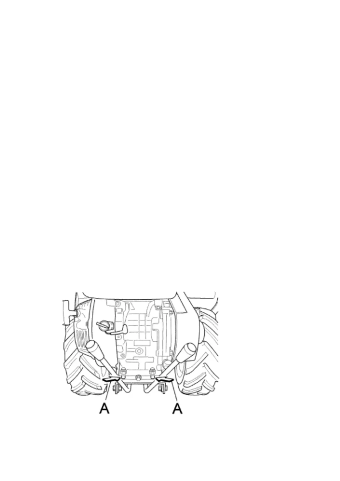
the belt does not work. Should the belt engage move the engine slightly towards
the front of the machine by unscrewing the fixing nuts (Fig. 13 Ref. A)
When retightening the nuts after making this adjustment make sure that the two
pulleys (Fig. 11 Ref. B, Ref. C) are perfectly aligned.
D3)
ROTOR ENGAGEMENT BELT
The rotor engagement belt should only be replaced and adjusted after having first
replaced the forward belt( point D2)
Remove the belt (Fig. 12 Ref. A) turning the engine pulley (Fig. 12 Ref. C) anti-
clockwise. Fit the new belt by slipping it onto the large pulley (Fig. 12 Ref. B) first,
then onto the engine pulley (Fig. 12 Ref. C). Then switch on the engine, making
sure that the rotor engagement lever (Fig. 1 Ref. D) is released and that in this
condition the belt does not work. Should the belt engage remove the pulley sup-
port screws (Fig. 14 Ref. A and B) and move the pulley support towards the ma-
chine handlebars. Then refit and adjust the rotor brake (Fig. 7 point C).
FIG. 11