20
Component Testing Procedures
15A TL Fuses for
208/230vac units
12ATL Fuses for 120vac
Power In terminals ..................................
Power Out terminals ...............................
Power In terminals ..................................
Power Out terminals………………………
120 VAC (SWA12)
240 VAC (SWA18 or 21)
240 VAC (SWA18 or 21)
If no power in,
check power
outlet. If no power
out, check fuses.
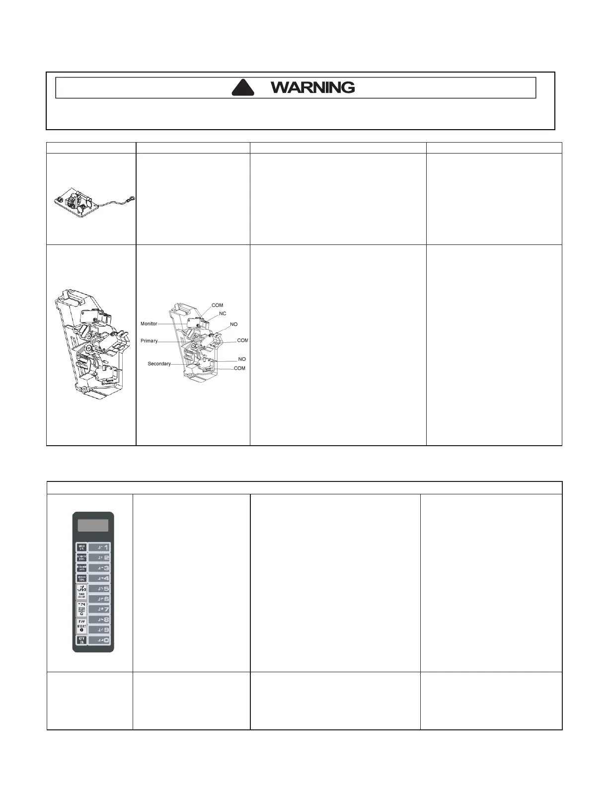
Interlock switch assembly
Disconnect wires to switch.
With door open measure resistance from:
Top Monitor – COM – NO ..................
Btm Monitor – COM – NO ………........
Top Primary – COM – NC …………….
Btm Primary – COM – NC ………….
Secondary – COM – NC ………. ........
With door closed measure resistance from:
Top Monitor – COM – NO....................
Btm Monitor – COM – NO ……….......
Top Primary – COM – NC………………
Btm Primary – COM – NC ……….........
Secondary – COM – NC …………........
Indicates continuity
Indicates continuity
Infinite
Ω
Infinite Ω
Infinite Ω
Infinite Ω
Infinite Ω
Indicates continuity
Indicates continuity
Indicates continuity
After verifying or replacing the module,
reconnect wires to switch and check
operation of monitor circuit before
Open door, Press and Hold pad 3 for 5
SERVICE appears in the display
seconds to enter service test mode.
Press Pad 1..................................................
Indicates number of hours
magnetron has been turned on
Press Pad 2..................................................
Indicates number of times
magnetron tube has been turned
Press Pad 3..................................................
Indicates number of door cycles
Press Pad 4..................................................
CLEAR (Press START pad to
reset service data.)
Press Pad 5..................................................
Indicates amperage (Top Mag)
Press Pad 6..................................................
Indicates amperage (Bottom Mag)
Press Pad 7..................................................
RESET (Clear Service Alarm)
Press Pad 8..................................................
Press Pad 9..................................................
Press Pad 0..................................................
Stop/Reset Pad ............................................
Error codes:
E-08 ..............................................................
E-09..............................................................
E-10..............................................................
Replace Control Board
Shorted or Open Keypad – Test
and replace if necessary
To avoid risk of electrical shock, personal injury or death, disconnect power to oven and discharge capacitor
before servicing, unless testing requires it.