Drive Power
BLU
C
-
24 Vdc - 3A/5.5A
Selected via Dip Switch 3
BRN
D
+
Encoder Signal
Rain Sensor
O
Contact
Dry contact input
P
Common
Q
Power supply output:
24 VDC 300 mA
R
S1
S2
Encoder Power
F
BLU
M
-
BRN
N
+
BLK
G
-
RED
H
+
RED
I
-
BLK
J
+
YEL
E
Encoder Requires Dip
GRN
F
YEL
K
GRN
L
Switch 1 ON
-
+
Copyright © Somfy SAS 12/2019 P-0036
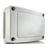
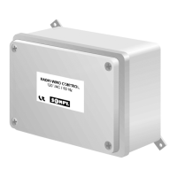
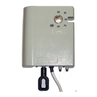
Pergola Tilt RTS Control Box
Connection Quick Start Guide
S T
External
antenna
PROG
button
+
ON
ON
ON
ON
ON
OFF
OFF
OFF
OFF
OFF
Switch 1
Switch 2
Switch 3
Switch 4
Switch 5
O
P
Q
R
Power
Output
Contact
B
A
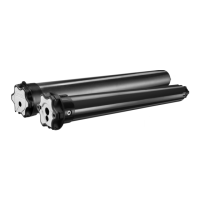
Drive
S2
Drive
S1
E
D
C
Power
supply
input
External antenna
S
Signal Conductor
T
GND Shielding braid
+
-
Status
The LED ashes every 4 seconds: Circuit board waiting.
The LED ashes rapidly: Command in progress.
Fault
The red LED light remains illuminated for 5 seconds: Current consumption threshold has
been exceeded or circuit board has heated up too much during an output command.
The red LED ashes: drive synchronisation fault.
The orange LED remains illuminated for several seconds: Backing-up the memory.
The orange LED ashes rapidly: Movement of a drive not permitted by a sensor action.
Wind
The orange LED remains illuminated: Wind
threshold has been exceeded.
The orange LED ashes rapidly: protection still
in progress for 15 minutes ater the threshold
last being exceeded.
Temperature
The orange LED remains illuminated: the ice threshold has been
exceeded. The Control is locked.
The orange LED ashes rapidly: protection still in progress for 15
DESCRIPTIONS OF CIRCUIT BOARD INDICATOR LIGHTS
1
2
3
4
S
T
Rain
The orange LED remains illuminated: The rain threshold has been
exceeded.
The orange LED ashes rapidly: protection still in progress for 15
minutes ater the threshold last being exceeded.
BEFORE YOU BEGIN: Power must be cut before wiring, setting the Dip Switches or making any wiring changes
OUTPUT Vdc
+
-
POWER SUPPLY
OUTPUT Vdc
+
-
S1
+
-
S2
+
-
Status
Fault
Wind
Rain
Temperature
Input Power Supply
A
-
24 Vdc power supply
B
+
input (SELV)
Switch 1
ON Drive
with encoder sensor
OFF
Drive
without encoder sensor
Switch 2 (Requires Switch 1 ON)
ON
Activates synchronization S1 and S2
OFF
Deactivates synchronization S1 and S2
Switch 3
ON
5.5 A max. per output
OFF
3 A max. per output
Switch 4
ON Activates the temperature sensor
OFF
Deactivates the temperature sensor
Switch 5
ON
Close in the event of wind
OFF
Open in the event of wind
DESCRIPTION & CONNECTIONS
minutes after the latest threshold is exceeded. Sensors locked out.
F
G
H
E
F
M
N
I
J
K
L
+
-
Contact
Rain
Sensor
DIP