Do you have a question about the Sommerkamp FT DX-500 and is the answer not in the manual?
Details the signal path and components within the receiver section.
Details the signal path and components within the transmitter section.
Describes the crystal-controlled carrier oscillators used for AM and CW modes.
Explains the crystal-controlled oscillators for crystal operation and band selection.
Details the VFO circuit using a silicon transistor for frequency generation.
Procedure for tuning the receiver for optimal performance.
Instructions for adjusting the bias on the final tubes.
Steps for pre-tuning the transmitter before final adjustments.
Procedure for peaking the transmitter output for maximum power.
Guidance for operating the transceiver in Single Sideband mode.
Details on measuring voltages and resistances for diagnostics.
Lists the necessary test equipment for service and alignment.
Identifies potential causes for unstable PA idling current.
Lists possible reasons for insufficient antenna load.
Potential causes for poor carrier suppression.
Troubleshooting distorted audio in transmitted signals.
Diagnoses issues with low or no drive to the final stages.
Potential causes for reduced receiver sensitivity.
Troubleshooting unstable VOX (Voice Operated Transmit) function.
Diagram and pinout for connecting accessories to the transceiver.
Table correlating VFO frequency with operating and local frequencies.
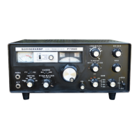
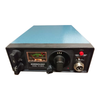
The FTDX-500 SSB Transceiver is a meticulously engineered and robust communication device designed for amateur radio enthusiasts. It offers versatile operation across multiple modes and bands, providing a comprehensive solution for both transmitting and receiving. The transceiver is self-contained, requiring only a microphone, a speaker, and an antenna for full functionality, making it a convenient and integrated station.
At its core, the FTDX-500 operates as a double-conversion receiver and a double-conversion exciter-transmitter, utilizing common oscillators, crystal filters, and IF stages to ensure efficient and stable performance. The receiver section begins with a signal from the antenna passing through an antenna relay and a trap coil, which helps to minimize interference from the first IF range. This signal is then amplified by the RF amplifier (V1, 6BZ6) and fed to the first receiver mixer (V201, 6CB6). A high-frequency oscillator injection signal from the local oscillator (V2, 6BA6) is also fed to this mixer, producing a product that is applied to a variable IF transformer. The output of this transformer (covering 5,220 to 5,720 Kc) is then sent to the second receiver mixer (V203, 6BE6). Here, a VFO injection signal is applied, resulting in a 3,180 Kc difference product that is fed to the crystal filter. The filtered signal is then amplified by the first IF amplifier (V204, 6BA6) and subsequent stages, eventually reaching the AM detector, AVC rectifier diodes, and the product detector (V213, 12AU7). The beat-frequency oscillator (V206, 12AU7) provides a signal to the cathode of V213, yielding the detected audio signal. The AVC rectifier circuit controls the gain of the RF and IF amplifier tubes to prevent overloading, while the detected audio is routed through a noise limiter circuit and the AF GAIN control (VR9) to the AF amplifier stages (V210, 6BM8) and finally to the output transformer.
The transmitter circuit initiates with microphone input connected to the first audio amplifier (V208A, 12AX7), then coupled to the second audio amplifier (V208B). The output from V208B is fed to the beam deflection electrode of V207, 7360, via the MIC GAIN control (VR-6). In TUNE mode, a tone oscillator (V212, 6U8) provides a signal to the second audio amplifier and the receiver AF amplifier for tune-up and sidetone monitoring. The carrier signal from V206, 12AU7 is fed to the control grid of V207, a balanced modulator. The output of the balanced modulator is coupled to the IF amplifier (V204, 6BA6) through the crystal filter (XF-201), which is centered at 3,180 Kc. This filter passes either the upper or lower sideband, depending on the MODE switch setting. The IF amplifier output is fed to the transmitter VFO mixer (V201, 6CB6), where it is converted to a 5,220 to 5,720 Kc single sideband signal by the tunable IF coil (L202). This signal then goes to the second mixer (V3, 6AH6), where it is combined with a high-frequency injection signal from the crystal oscillator (V2, 6BA6) to produce the desired transmitting frequency. The output from the second mixer drives the driver tube (V4, 5763), which in turn drives the final linear amplifier tubes (V5 and V6, 6KD6s). The final output is fed to a pi-section network (L15, PLATE, and LOAD capacitors) before reaching the antenna through transmit/receive relay contacts. Both driver and final stages are neutralized for stability.
The Automatic Level Control (ALC) circuit is integrated into the grid circuit of the final tubes. When the RF driving voltage is sufficient to drive the grids positive, current is drawn, and the signal is detected, producing an audio envelope. This audio is rectified by the ALC rectifier, generating a negative DC voltage. This voltage, filtered and time-constant controlled by C61, C62, R29, and R30, regulates the gain of V204, allowing for a high average level of modulation without excessive distortion. The ALC voltage is grounded in CW and TUNE modes.
The VOX (Voice Operated Transmit) system uses the second microphone amplifier output (V208) coupled through the VOX GAIN control to the grid of V209A, 12AU7, and then to the VOX rectifier. The positive DC output from the rectifier actuates the VOX relay amplifier tube (V209B, 12AU7), which in turn actuates the VOX relay (RL1). This relay controls muting, bias voltage, metering, clarifier, and remote socket grounding during transmit. The ANTITRIP circuit provides a threshold voltage to prevent loudspeaker output from triggering the transceiver into transmit. Receiver audio output is connected via the ANTITRIP control (VR8) to a rectifier, producing a negative DC voltage that provides the necessary antitrip threshold.
The transceiver incorporates six oscillators: two carrier oscillators (crystal controlled at 3,178.4 or 3,181.5 Kc), two high-frequency crystal oscillators (one for crystal-controlled operation, TR701, 2SC372, and another for band selection, V2, 6BA6), a variable frequency oscillator (VFO) using TR401 and TR402 (2SC372) operating from 8,400 to 8,900 Kc, a tone oscillator (for CW and TUNE modes, ~8000 cps), and a crystal calibrator (TR301, 2SC367 for 100 Kc, with a 25 Kc multivibrator, TR302).
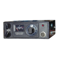
The FTDX-500 offers a range of controls and switches for flexible operation. The SELECT switch determines the operating frequency source: INT for the main tuning dial or EXT for an external VFO, allowing independent transmit/receive frequencies. It also provides crystal-controlled operation via CH-1 to CH-4. The FUNCTION switch manages the transceiver's power and calibration modes: OFF for power down, STBY for all voltages applied in receive, CAL 100 KC and CAL 25 KC for calibrator activation, MOX for transmit energization, PTT for push-to-talk, and VOX for voice-controlled operation.
The MODE switch selects the operating mode: USB/LSB for sideband, TUNE for transmitter tune-up, CW for code operation, and AM for carrier and one sideband operation. RF GAIN controls the gain of RF and IF stages, while AF GAIN adjusts the receiver audio amplifier gain and disconnects the automatic noise limiter when pulled. The MAIN TUNING dial sets the operating frequency, and the BAND switch selects the appropriate coils for the desired band. The CLARIFIER varies the VFO frequency for receiver incremental tuning and acts as a vernier for the main dial.
The METER switch allows selection of various readings: PA cathode current, relative power output, or plate current of the ALC-controlled stage. MIC GAIN controls microphone gain for transmit and tone signal input for tune-up. The AGC switch changes receiver AGC release time constants. PRESELECT acts as a preselector for the receiver and tunes the driver stages for the transmitter. PLATE tunes the plate circuit of the PA tubes, and LOADING tunes the output circuit of the PI network.
Initial setup involves checking for visible damage, ensuring tubes and crystals are seated, and verifying tuning control freedom. Speaker and antenna cables are connected, and the supply voltage is matched. After setting the FUNCTION switch to STBY and MIC GAIN to counterclockwise, the S-meter will slowly come to full scale during warmup. Meter adjustment includes setting ALC for full scale and S-meter zero with the antenna disconnected. Bias adjustment involves setting MODE to USB, METER to IC, FUNCTION to MOX, and adjusting the BIAS potentiometer for approximately 50 mA PA plate current.
Receiver tuning involves adjusting AF GAIN for receiver noise, peaking PRESELECTOR for maximum S-meter reading, and using the CAL 100 Kc or 25 Kc positions for dial calibration. The red scale on the main dial corresponds to the red-marked bands on the BAND switch, starting from 500 Kc.
Transmitter tuning requires setting controls to INTERNAL, STBY, TUNE, MIC GAIN fully counterclockwise, AF GAIN to normal listening level, METER to IC, CLARIFIER OFF, and selecting the desired BAND, PLATE, and LOADING positions. The procedure involves adjusting PRESEL for maximum receiver noise, turning FUNCTION to MOX with the meter in IC position, rotating MIC GAIN for slight meter rise (50 mA), peaking PRESEL, dipping PLATE, and returning FUNCTION to STBY. Final peak tuning is done by setting the meter to P.O., FUNCTION to STBY, MODE to CW, then momentarily setting FUNCTION to MOX (10 seconds max) to adjust PRESEL, LOADING, and PLATE for maximum meter reading, repeating until maximum output is achieved. For SSB operation, the key jack must be removed. MIC GAIN is adjusted with the METER in ALC position until the meter kicks to midscale during speech. For VOX operation, the VOX GAIN control is advanced until voice actuates the transceiver, and ANTITRIP is adjusted to prevent speaker output from triggering VOX. DELAY control adjusts the release time constant. For CW operation, a key is connected, and the MODE switch is set to CW. For AM operation, the key jack is removed, MODE is set to AM, and MIC GAIN is adjusted for slight kicks on speech peaks, not exceeding 150 mA.
The FTDX-500 is designed for reliability, with alignment and calibration performed at the factory. However, for service, extreme caution is advised due to dangerous voltages. All power must be disconnected before working inside the chassis, and high voltage capacitors should be discharged. Realignment is generally not required unless major components are replaced or significant issues arise.
For troubleshooting, a table of voltages and resistances at all tube sockets is provided, measured with a VTVM with all tubes installed. All measurements are taken from socket pins to ground. A transistor voltage stabilizer (VR-202) should be adjusted to exactly 9 volts.
Common issues and their possible causes are listed in a troubleshooting guide. For instance, an unstable PA idling current might indicate defective V5/V6 or bias supply issues. Insufficient load could be due to improper PRESELE tuning, BAND switch setting, antenna resonance, or defective components. Insufficient carrier suppression might point to a defective V207, improper carrier balance control, or defective crystals. Distorted transmitted signals could be caused by excessive MIC GAIN, defective V7, D2/D3, or incorrect neutralization. Insufficient drive or no drive might stem from a defective rectifier, V204, V201, V3, V4, V5, or a defective crystal. Low receiver sensitivity could be due to defective antenna relay contacts or defective V1, V201, V203, V204, V205. VOX instability might be caused by a defective V209 or improper setting of VOX GAIN & ANTITRIP controls.
To access the chassis for service, six screws around the cabinet and two on the bottom must be removed. The chassis can then be pushed forward until the front frame slides out, allowing it to be carefully slid out of the cabinet while holding the front panel.
Transmitter alignment involves disconnecting high voltage and screen voltage leads, connecting a VTVM RF probe to V5 pin 5, setting MODE to USB or LSB, FUNCTION to MOX, and adjusting carrier balance potentiometer VR201 for minimum VTVM indication. MIC GAIN is advanced, MODE is set to TUNE, and PRESELE is adjusted for maximum VTVM reading. Subsequent steps involve adjusting slugs of L203, L204, and L202 for peak VTVM readings across different tuning dial positions. Band-specific adjustments for L901, L1001, L905, L1005, L3, and various TC capacitors are detailed. Spurious radiation is minimized by adjusting Tc-203 and TL-401.
Receiver circuit alignment, if transmitter circuits are already aligned, primarily focuses on the last IF stage transformer L205, antenna input transformers L801-L805, trap coils L806 and L906, and S-meter zero set. A signal generator is used to inject signals at specific frequencies, and PRESELE, L801-L805, L806, L906, and L205 are adjusted for peak S-meter readings or minimum S-meter readings for trap coils. The S-meter zero set is adjusted with the RF GAIN control fully clockwise and the signal generator disconnected.
The manual also provides signal level tables for both transmitter and receiver, indicating nominal voltages and frequencies at various test points to aid in troubleshooting and verification. These values are nominal and may vary by ±20% without degrading performance.
| Modes | SSB, CW, AM |
|---|---|
| Type | HF Transceiver |
| Sensitivity | 0.5 uV for 10 dB S/N |
| Selectivity | 2.4 kHz at -6 dB |
| Dimensions | 160 mm |