Do you have a question about the Sommerkamp TS-340 DX and is the answer not in the manual?
Instructions for carefully unpacking the transceiver and checking for damage.
Details receiver sensitivity, selectivity, and features like deluxe filters and squelch control.
Highlights transmitter efficiency, ALC circuit for talk power, and SSB signal stability.
Specifies the built-in power supply requirements for the transceiver.
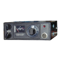
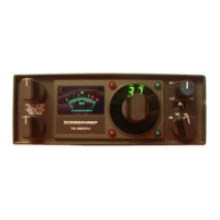
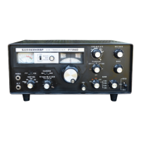
Lists and describes controls on the front panel of the transceiver.
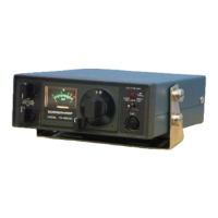
Lists and describes connectors and controls located on the rear panel.
Details the push-to-talk switch and Vol-U-Mic control on the microphone.
Combines power on/off function with receiver volume adjustment.
Describes the Vol-U-Mike for convenient remote volume adjustment.
Explains how to use the squelch control to eliminate background noise.
Details the function of the channel selector for choosing frequencies.
Discusses adjusting microphone sensitivity for optimal transmission.
Explains how to adjust receiver sensitivity using the RF Gain control.
Describes the AM, LSB, USB modes and their corresponding indicator lights.
Details the clarifier's role in fine-tuning reception frequency in SSB and AM modes.
Explains the TX indicator LED and when it illuminates.
Describes the High/Low band switch for operating frequencies.
Guides on using the SWR meter for calibration and measurement.
Explains the instant channel change function for emergency Channel 9.
Details the CW switch for connecting a Morse key device.
Describes how to read the S/RF meter in receive and transmit modes.
Details the noise blanker and ANL circuits for noise suppression.
Lists and describes DC, Key, External Speaker, and Antenna connectors.
Explains how to use the microphone for transmitting and speaking.
Provides instructions for negative ground systems and wiring connections.
Outlines essential steps before operating the unit, including connections and control settings.
Lists compatible antenna types and the standard connector used.
Covers base station and mobile antenna installation considerations.
Discusses vertical whip and quarter-wave whips for mobile use.
Advice on choosing a location and connecting power for mobile units.
Recommendation for a regulated power supply for base station use.
Illustrates the components and method for mounting the transceiver bracket.
Lists semiconductors, frequency range, modes, controls, connectors, and physical details.
Details sensitivity, selectivity, AGC, squelch range, and audio characteristics.
Outlines RF output power, suppression, and current drain for SSB and AM modes.
Step-by-step procedure for aligning the receiver section for optimal performance.
Procedures for adjusting power, modulation, and suppression for the transmitter.
Identifies the transceiver, antenna, and coaxial cable as key components.
Stresses the necessity of tuning the antenna for maximum performance.
Explains the role of coax cable in transferring power and maintaining system balance.
Defines SWR and its impact on power transmission and range.
Guides on using the transceiver's meter as a tool for antenna tuning.
Details the process of tuning an antenna using an external SWR meter.
Provides practical tips for antenna maintenance, connections, and SWR checking.
Lists the connections for the 7-pin DIN accessory jack.
Shows wiring diagrams for headsets, microphones, and speakers.
| Brand | Sommerkamp |
|---|---|
| Model | TS-340 DX |
| Category | Transceiver |
| Language | English |