4
• The SONANCE TV Box is designed to be installed “Above or
below your TV Bracket easy access to the contents inside
the box.
• After you have determined the center location of your
television, and have determined where your TV bracket
will be installed, you can now move onto determining the
location of the Sonance TV Box. See Figure 3 for positioning
ideas for the The SONANCE TV Box.
Figure 3
SONANCE TV BOX INSTALLATION
1. Determine the center location of your TV first. Use a
stud finder to locate the space in-between two studs
that are as close to the center of your TV as possible.
2. Mark the two studs on each side of the location
determined to mount the wall box. It is recommended
to mound the wall box as close to the center of the TV
as possible. Measure between the two marked studs to
confirm that the SONANCE TV Box will fit (width >= 13”).
3. Use a drywall saw to cut a hole 13 Inches wide and 14
inches tall to mount the SONANCE TV Box.
4. Test fit the SONANCE TV Box into the opening that was
just cut and make any needed modifications to the opening
at this time.
5. DO NOT SECURE THE SONANCE TV BOX WITH
SCREWS AT THIS POINT. CONTINUE TO
INSTALLATION OF MAG6 LCR BELOW.
13.00 IN
[330.2 mm]
14 IN
[355.6 mm]
Figure 4 - Sonance TV Box cutout dimentions
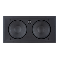
INSTALLATION - MAG6 LCR
At this point you should have three holes cut in your wall.
Two speaker holes and one TV box hole. Run your speaker
wire from each speaker to the SONANCE TV Box location.
Sonance speakers feature integral Roto-Lock
®
mounting
system for quick mounting directly into existing walls.
1. Fish speaker wire through the wall into the SONANCE
TV Box openings using one of the provided knock outs if
needed. This needs to occur before the speaker is in place.
2. Strip 1/4” – 1/2” (6mm – 12mm) of insulation from each
speaker wire. Twist the strands or tin the exposed wire
with solder to ensure that there are no stray strands.
NOTE: SONANCE RECOMMENDS USING BEST BUY’S
PROFESSIONAL INSTALLATION SERVICE FOR ANYONE
NOT FAMILIAR WITH THE PROCESS OF RETROFITTING
LOW VOLTAGE WIRING
3. The speaker’s terminals are spring-loaded. Push the top of
each terminal down to open the connector and insert the
exposed wires into the holes in the spring terminals. The
speaker’s positive spring terminal is labeled with a red dot;
the negative spring terminal is labeled with a black dot.
Double check that you connected amplifier “+” to speaker
“+” and amplifier “–” to speaker “–”.
4. Make sure all the Roto-Lock toggle feet are retracted so
that they are tucked within the mounting hole’s border.
Insert the speaker into the hole in the wall (Figure 5).
The Roto-Lock system can accommodate a wall material
thickness of 1-1/2” (38mm). The Roto-Lock feet caps can be
removed for installations in double drywall.
NOTE: STRAY STRANDS THAT TOUCH EACH OTHER CAN
CAUSE A SHORT-CIRCUIT THAT CAN DAMAGE THE AMPLIFIER.
Install Option 1
Install Option 2
Roto-Lock
Clamps
(retracted)
5. Tighten the screws on the front of the speaker bae.
The Roto-Lock toggle feet will automatically rotate into
position and begin clamping the speaker (Figure 6).
When you notice resistance on the screws the speaker
has been clamped successfully.
6. IMPORTANT: Always use low torque settings; NEVER
over-tighten.
NOTE: ADJUST THE TENSION OF THE ROTO-LOCK CLAMPS
SO THAT THE SPEAKER FRAME IS FLAT. THIS WILL HELP
ENSURE THAT THE GRILLE CONTACTS THE WALL ALL THE
WAY AROUND THE SPEAKER FOR A PROPER FIT.
Roto-Lock
Clamps
(retracted)
Roto-Lock
Screws
Figure 5
Figure 6
7. The micro-trim grille is held in place by several small,
powerful magnets on the speaker frame. Place the grille
against the speaker and the magnets will hold it firmly in
place. When properly installed, the grille trim should make
contact with the wall all the way around the speaker.
8. Continue with the install of the Sonance TV Box below.
SONANCE TV BOX
INSTALLATION (CONT.)
6. Insert the provided wire grommets into the knockout
holes to hold and protect your speaker wires.
7. Use the provided #6 x 1 5/8” Phillips wood screws to
mount the SONANCE TV Box to the studs in the wall.
NOTE: IF THE SONANCE TV BOX DOES NOT SPAN EVENLY
ACROSS BOTH STUDS USE DRYWALL ANCHORS TO ANCHOR
THE SIDE OF THE BOX THAT DOES NOT TOUCH THE STUDS
 Loading...