Input/Output Lights
When each channel is active, the LED will light green as long as a
ZPNUHSPZWYLZLU[0UW\[6\[W\[3,+ZISPURPUNYLKPUKPJH[L[OH[[OL
HZZVJPH[LKJOHUULSPZILPUNV]LYKYP]LU0UW\[6\[W\[3,+Z[\YUPUN
ZVSPKYLKPUKPJH[L[OH[[OLHTWSPÄLYPZPUWYV[LJ[TVKL>OPSLPU
protect mode the LED lights will periodically light green to retest the
output to determine if the issue has been resolved. Protect mode
JV\SKILJH\ZLKI`HZOVY[PU[OL^PYLV]LYOLH[PUNVM[OLHTWSPÄLY
VYV[OLYPU[LYUHSWYVISLT^P[O[OLHTWSPÄLY
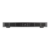
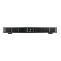
Front Panel
Power Button
;OLWV^LYI\[[VU[\YUZ[OLHTWSPÄLYVUHUKVќ>OLU[OL:VUHUJL
llogo power button is engaged, the power button is illuminated
ZVSPK^OP[L;OPZTLHUZHTWSPÄLYOHZWV^LYHUKPZ[\YULK65HUK
ready to operate. When the Sonance logo is slightly dimmed, the
HTWSPÄLYPZPUZ[HUKI`TVKL>OLU[OL:VUHUJLSVNVISPURZ^OP[L
[OLHTWSPÄLYWV^LYZ\WWS`PZPU[OLYTHSWYV[LJ[PVU0U[OPZZP[\H[PVU
the channel LEDs will also illuminate red, indicating that the power
supply is in thermal protection mode.
NOTE: UPON INITIAL POWER UP, THERE WILL BE A 9-12 SECOND DELAY
BEFORE SOUND IS HEARD DURING THE BOOT UP CYLE. THE INDICATOR
LEDS WILL ILLUMINATE RED, THEN GREEN, THEN GO OUT. THIS IS NORMAL.
NOTE: WHEN ANY OF THE LEDS ARE RED, TURN THE AMPLIFIER OFF
IMMEDIATELY. DETERMINE THE CAUSE OF THE PROBLEM BEFORE
TURNING THE AMPLIFIER BACK ON.
Volume Level Control
,HJOJOHUULSVU[OLHTWSPÄLYOHZ]VS\TLHKQ\Z[TLU[ZJVU[YVSSLK
in the SonARC software or on the front panel recessed volume
JVU[YVSZ6\[W\[]VS\TL^PSSYLÅLJ[[OLVW[PVUSHZ[HKQ\Z[LK
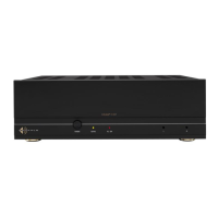
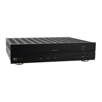
Rear Panel
Line Inputs/Loop Outputs
;OL+:74200HTWSPÄLYOHZSPULPUW\[ZHUKSVVWV\[W\[Z
;OLSVVWV\[W\[ZHYLUVUI\ќLYLK[OLTH_PT\TU\TILYVM
HTWSPÄLYZ[OH[JHUILSVVWLK[VNL[OLY^PSSKLWLUKVU[OLV\[W\[
capability of your source component
Speaker Connections
;OLYLTV]HISLISVJRJVUULJ[VYZ\ZLKVU[OL:VUHTWHTWSPÄLYZ
will accept up to 12 gauge wire. Follow the connection layout on
[OLYLHYWHULSVM[OLHTWSPÄLY4HRLZ\YLUVIHYL^PYLZJVTLPU
JVU[HJ[^P[O[OLHTWSPÄLYJOHZZPZ>OLUIYPKNPUNJOHUULSZ\ZL[OL
two outside connections on each connector. The positive wire from
the speaker should be on the left side connection and the negative
connection should be on the right side. To avoid shock or shorts
use the included block connector protective cover (see Figure 5).
CAUTION: FOR CONTINUED PROTECTION AGAINST FIRE, REPLACE THE
FUSE WITH ONLY THE SAME TYPE AND RATING.
Power Cord
The Sonamp DSP 2-750 MKII features a removable power cord.
Plug the female end of the power cord into the Power Cord
*VUULJ[VYVU[OLHTWSPÄLYYLHYWHULSHUKWS\N[OLTHSLLUKPU[VH
grounded wall socket.
+656;WS\N[OLHTWSPÄLY»ZWV^LYJVYKPU[VHJVU]LUPLUJLV\[SL[
on any other audio or video component. If you need to use an
extension cord, use only a heavy duty (14 GAUGE OR LARGER)
L_[LUZPVUJVYK[VH]VPKZ[HY]PUN[OLHTWSPÄLYVM[OLJ\YYLU[
necessary for full operation.
-PN\YL!:VUHTW+:74200(TWSPÄLY-YVU[7HULS=PL^
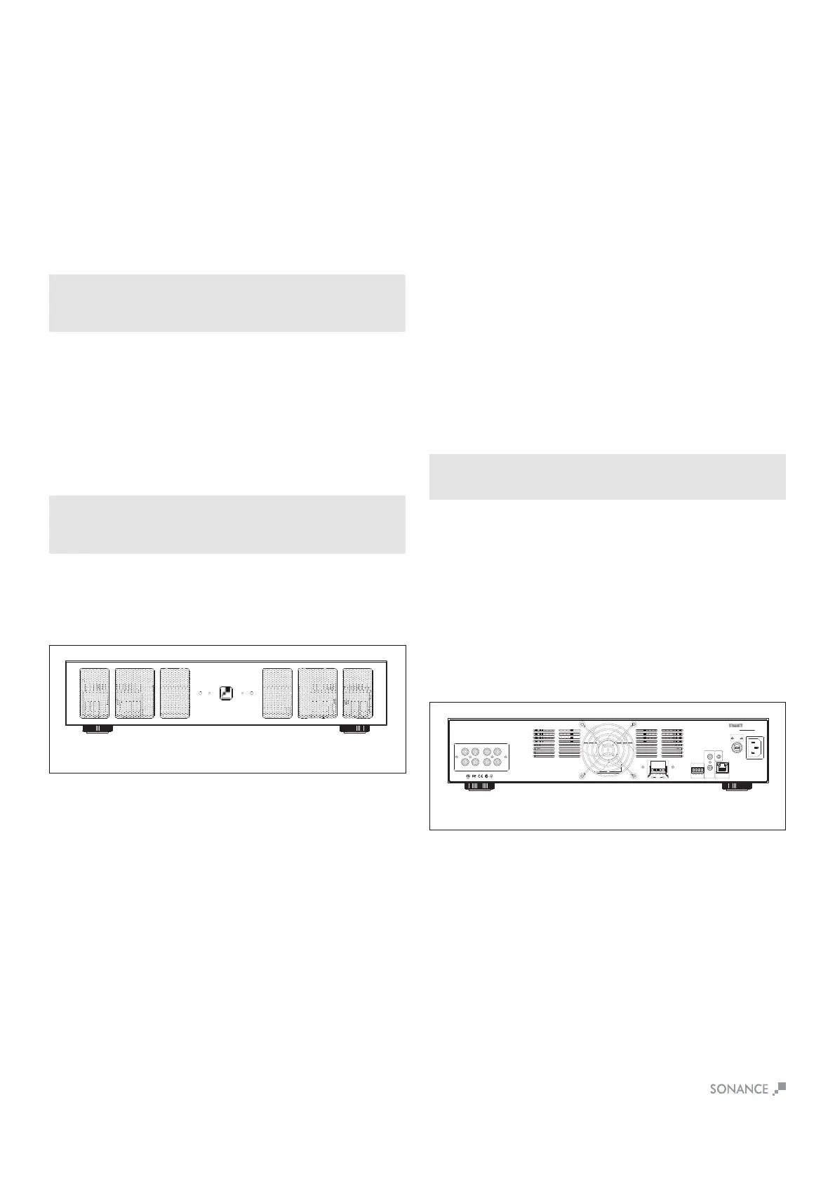
-PN\YL!:VUHTW+:74200(TWSPÄLY9LHY7HULS=PL^
Auto On - Voltage In/Out Trigger
;OL:VUHTWHTWSPÄLYZJHUIL[\YULKVUHUKVќ\ZPUN]VS[Z
AC or DC. The Voltage Output supplies a 12 volt DC signal to
JVU[YVSHKKP[PVUHSHTWSPÄLYZVYV[OLYLX\PWTLU[
IR Control
IR control is established via the 3.5mm mono mini input jack on the
YLHYVM[OLHTWSPÄLY09JVTTHUKZPUJS\KL]VS\TLT\[LNYV\W
WV^LYHUKPUW\[VW[PVUZ09JVU[YVSZNSVIHS6U6ќNYV\W]VS\TL
muting and input source selections. Connectivity can be seen with
IR status light.
IP Control
07JVU[YVSPZ]PH[OL91PUW\[07JVU[YVSZWV^LY6U6ќ]VS\TL
muting and input source selections for either global control or
group control.
AC Fuse Holder
To replace the fuse, unplug the power cord from the Power Cord
Connector and use a screwdriver to remove the fuse holder.
DSP 2-750 - 15 amp AC.
1L
1R
DSP 2-750 MKII
1-R1-L 2-R2-L
IN IN
OUTOUT
DSP 2-750 MKII
S/N
1 - RIGHT
1 - LEFT
++
__
+
_
BRIDGE
4 Ğ MIN
+
+
__
VOLTAGE TRIGGER
3-30 volts AC/DC
IN OUT
IN
OUT
IR
CONTROL
IR
STATUS
TCP/IP
DEFAULT IP
192.168.1.50
T10AL/250VAC
CAUTION
REPLACE FUSE ONLY WITH SAME
TYPE AND RATING OF FUSE
ATTENTION
REMPLACER UNIQUEMENT AVEC
LE MEME TYPE ET CALIBRE DU
FUSIBLE
AC 100-120V ~ 60Hz
AC 220-240V ~ 50Hz
CAUTION
RISK OF ELECTRIC SHOCK
DO NOT OPEN
AVIS
RISQUE DE CHOC ELECTRIQUE
NE PAS OUVRIR
 Loading...