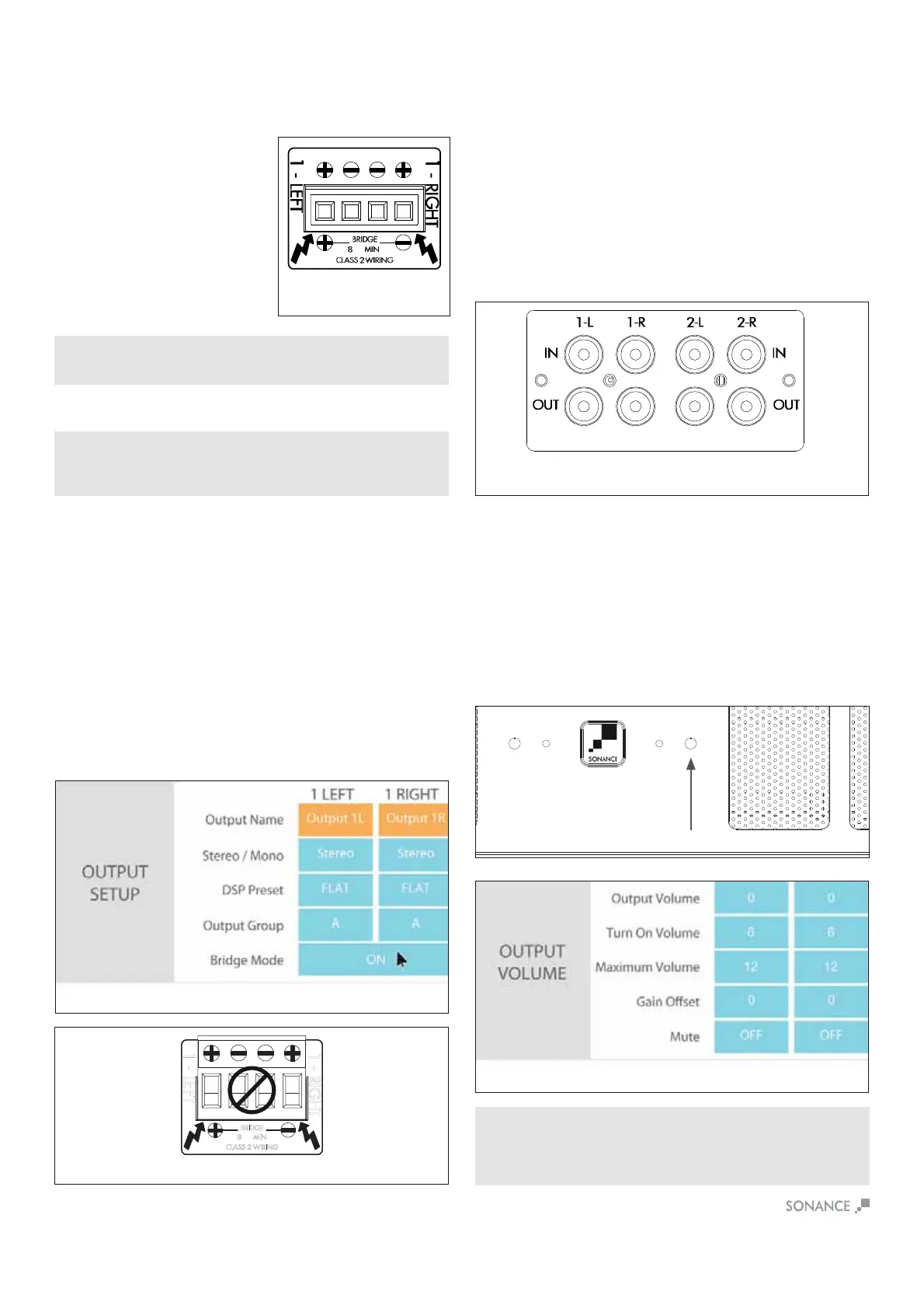
1L
1R
DSP 2-750 MKII
7
%ULGJLQJ&KDQQHOV'630.,,
-PN\YL!=VS\TL3L]LS*VU[YVS
-PN\YL!)YPKNPUN*OHUULSZ
Volume Level Control
Volume can be controlled from the individual recessed volume level
control screws, located on the front panel and from SonARC (see
Figure 13). These volume controls balance the desired sound levels
WLYJOHUULS=VS\TLJHUILJVU[YVSSLK[OYLLKPќLYLU[^H`Z^P[O
SonARC v2 (see Figure 14).
1. Output volume 2. Turn on volume 3. Maximum volume
Output volume ranges between -70 to 12. The volume level
controls are set at +12 by default.
6RXUFH&RQQHFWLRQV'630.,,
On the left side of the rear panel are the audio inputs for the left
and right channels. In addition to the left and right inputs there are
also loop outputs for each channel. The loop outputs allow multiple
HTWSPÄLYZ[VZOHYLJVTTVUH\KPVZV\YJLZ;OLSVVWV\[W\[ZVU
[OLHTWSPÄLYZHYLUV[I\ќLYLK;OLU\TILYVMHTWSPÄLYZ[OH[JHU
be connected in series will depend on the output level of your audio
ZV\YJL;OLZV\YJLJVUULJ[LK[V[OL3,-;HUK90./;305,05
0UW\[ZWHZZ[OYV\NO[OL3,-;HUK90./;305,6\[W\[Z
(see Figure 12).
1 - LEFT
1 - RIGHT
BRIDGE
8 ёMIN
CLASS 2 WIRING
-PN\YL!:VU(9*7HNL0U6\[:L[[PUNZ6\[W\[=VS\TL
Speaker Connections
For the best sound you should use
premium speaker wire that complies
^P[OÄYLYH[PUNJVKLZ)LZ\YL[V
check local codes governing wire
that may be installed within walls or
JLPSPUNZ:VUHTWHTWSPÄLYZHYL
stable with any reputable brand of
speaker wire or cable. The Sonamp
HTWSPÄLYZ\ZLZWLHRLYISVJR
connectors that can accommodate
up to 12 gauge wire (see Figure 9).
NOTE: ALWAYS CHECK LOCAL BUILDING CODES BEFORE INSTALLING
WIRE IN WALLS OR CEILINGS.
Figure 9
Speaker Connections
Bridging channels is accomplished using the SonARC v2 software.
6U[OLZLJVUKWHNLPU[OLZVM[^HYL\UKLY056<;:L[[PUNZNV[V
the output setup area to bridge mode and make your selections
with the drop down buttons.
<ZL[OLSLM[H\KPVPUW\[^OLUVWLYH[PUN[OLHTWSPÄLYZV\[W\[PU
bridge mode (see Figure 10).
:LSLJ[65PU[OLIYPKNLTVKLZLLÄN\YL
*VUULJ[[OLZWLHRLY»Z¸¹SLHK[V[OLSLM[ZPKLVM[OLJVUULJ[VY
THYRLK¸¹ZLL-PN\YL
*VUULJ[[OLZWLHRLY»Z¸¶¹SLHK[V[OLYPNO[ZPKLVM[OLJVUULJ[VY
THYRLK¸¹ZLL-PN\YL
5. Connect the line level audio input to the LEFT channel input on
[OLHTWSPÄLY
IMPORTANT: THE MINIMUM SPEAKER IMPEDANCE FOR BRIDGED
OPERATION IS 8 OHMS. DO NOT OPERATE A ZONE IN THE BRIDGED MODE
INTO A SPEAKER THAT IS LESS THAN 8 OHMS NOMINAL IMPEDANCE.
-PN\YL!)YPKNPUN*OHUULSZ
-PN\YL!:VUHTW+:74200
3LM[HUK9PNO[3PUL0UW\[Z6\[W\[Z
IMPORTANT: USE CAUTION WHEN SETTING VOLUME LEVELS EITHER ON
THE AMPLIFIER OR AN AUDIO SWITCHER AS NOT TO OVERDRIVE AND
POSSIBLY DAMAGE SPEAKERS. VERIFY ALL SOURCES AS OUTPUT
VOLTAGE VARIES FROM DEVICE TO DEVICE.
 Loading...