0449P300 Installation Superstatic 449 DE EN 19-01-2012
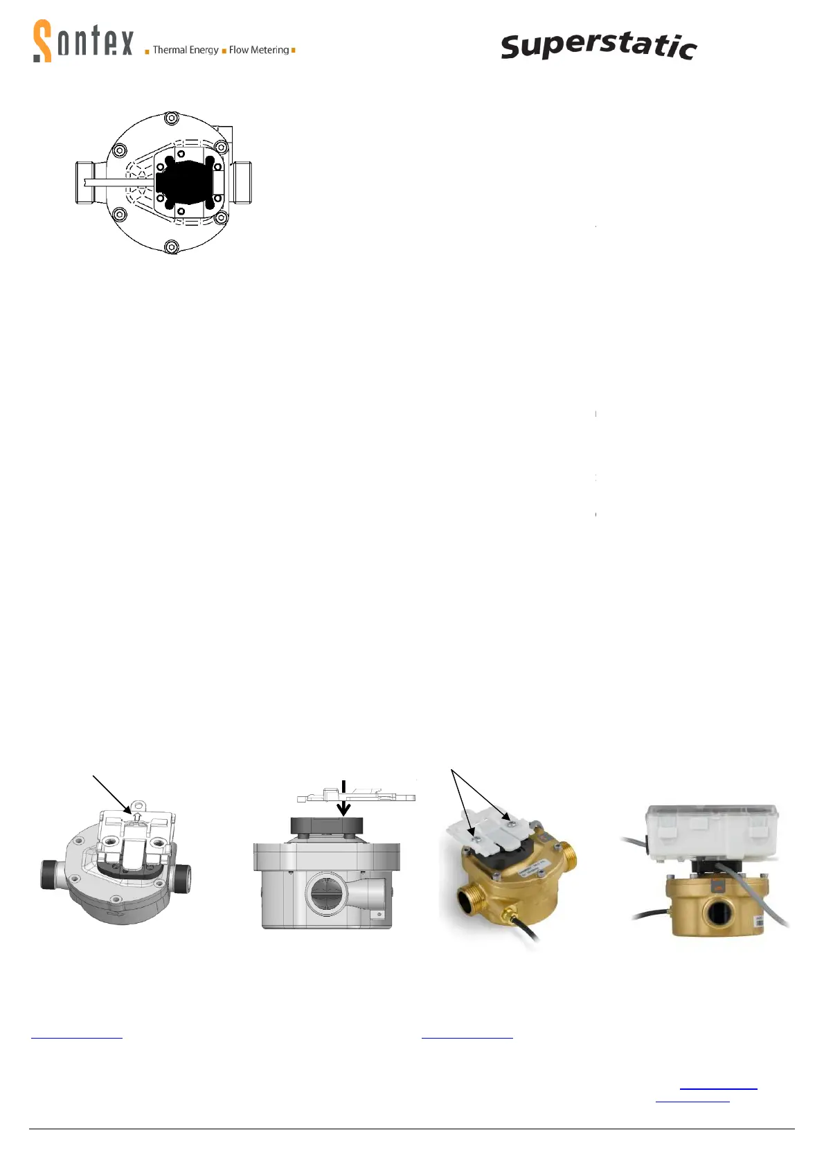
Einbaulage horizontal - Horizontal mounting p
Allgemeiner Einbauhinweis:
Nach dem Einbau und vor der Inbetriebnahme, System > 10 min. spülen
um Lufteinschlüsse zu vermeiden.
Bedingungen zur Einhaltung de
- Die Temperaturfühler sind symmetrisch in den Vor-
vorzugsweise direkt einzubauen. Bei Verwendung von Tauchhülsen mü
sen diese ausschließlich für
die verwendeten Temperaturfühler konform
tätsuntersucht sein. Die Vor-
und Rücklauffühler müssen auf den Tauc
hülsenböden aufsitzen. Einbaustellen im Durchflusssensor können unter
symmetrischem Einbau der Temperaturfühler genutzt werden.
rischer Ein
bau der Temperaturfühler ist NICHT zulässig.
- Für die austauschbaren
konformitätsgekennzeichnete
beträgt deren maximale Länge,
m, für die Leitungsquerschnitte gilt EN 1434-
2. Deren Anschluss erfolgt
die gekennzeichneten Anschlussbereiche unter Beachtung der elektr
schen Kompatibilität Pt 100 bzw. Pt 500 des Rechenwerkes.
- Eine gerade Rohrstrecke von 3 DN ist vor dem
halten.
-
Die Auswahl der Batterie hat so zu erfolgen, dass die
die Länge der geplanten Einsatzdauer und 1 Jahr Lagerfrist eine Verso
gung mit Hilfsenergie gestattet.
- Angaben zur Messb
eständigkeit erfolgen unter den Bedingungen einer
Wasserzusammensetzung gemäß AGFW-
Anforderungen FW 510. Im Fa
le ab
weichender Zusammensetzungen muss das Messgerät ausgebaut
und regelmäßigen Instandsetzungen gemäß der Instandsetzu
der Firma Sontex unterzogen werden.
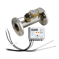
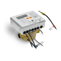
Rechenwerkmontage
Für die Rechenwerkmontage
auf dem Durchflusssensor sind im Lieferu
fang 2 Schrauben enthalten, mit denen
Rechenwerkes in 4 verschiedenen Positionen, jeweils um 90° gedreht,
dem Durchflusssensor montieren lässt.
Die Halterung muss auf dem Durchflusssensor
so montiert sein, dass der
Pfeil auf der Halterung sichtbar ist.
0449P300
Für technische Unterstützung wenden sie sich an die
tungen oder direkt an Sontex SA.
Hotline Sontex:
sontex@sontex.ch
+41 32 488 30 04
Technische Änderungen vorbehalten
Declaration of conformity
Die detaillierte Konformitätserklärung zum Herunterladen finden Sie auf unserer Homepage
The detailed declaration of conformity can be found and downloaded on our homepage
12
Sontex SA, 2605 Sonceboz, Schweiz, Switzerland
Vertical mounting position
Nach dem Einbau und vor der Inbetriebnahme, System > 10 min. spülen
General notice for mounting:
After mounting and before commissioning purge system >
bubbles.
vorzugsweise direkt einzubauen. Bei Verwendung von Tauchhülsen mü
s-
die verwendeten Temperaturfühler konform
i-
und Rücklauffühler müssen auf den Tauc
h-
hülsenböden aufsitzen. Einbaustellen im Durchflusssensor können unter
symmetrischem Einbau der Temperaturfühler genutzt werden.
Asymmet-
bau der Temperaturfühler ist NICHT zulässig.
konformitätsgekennzeichnete
n Temperaturfühler
- und Rücklauf, 15
2. Deren Anschluss erfolgt
an
die gekennzeichneten Anschlussbereiche unter Beachtung der elektr
i-
schen Kompatibilität Pt 100 bzw. Pt 500 des Rechenwerkes.
u-
Die Auswahl der Batterie hat so zu erfolgen, dass die
se mindestens über
die Länge der geplanten Einsatzdauer und 1 Jahr Lagerfrist eine Verso
r-
eständigkeit erfolgen unter den Bedingungen einer
Anforderungen FW 510. Im Fa
l-
weichender Zusammensetzungen muss das Messgerät ausgebaut
und regelmäßigen Instandsetzungen gemäß der Instandsetzu
ngsrichtlinie
Conditions to comply with the directive 2004/22/EU (MID)
The temperature sensors have to be
return and preferably without pockets. If using pockets they must be in a
cordance with the conformity declaration. Flow and return sensors must
be mounted to the bottom of the pockets. Installation places in the flow
sen
sor can be used with the symmetrical installation of the temperature
sensor pair.
Asymmetrical mounting of the temperature sensor is
NOT permitted.
-
For the exchangeable temperature sensor pairs according to MID the
maximum equal length is 15 m.
1434-2. The c
onnection to the integrator according to terminal connection
on page 2 by respecting the electrical compatibility Pt 100 and Pt 500 of
the integrator.
- A s
traight section of piping of 3 DN in flow of any flow
respected.
-
The selection of the battery has to take placed in such a way that it pe
mits at least a supply of auxiliary energy over the duration of the applic
tion plus 1 year storage period.
-
Information about the measuring stability is
water measurement in accordance with AGFW requirements FW 510. In
case of deviating compositions the measuring instrument must be submi
ted to periodic control according to the guidelines of Sontex.
auf dem Durchflusssensor sind im Lieferu
m-
im Rücken des
Rechenwerkes in 4 verschiedenen Positionen, jeweils um 90° gedreht,
auf
so montiert sein, dass der
Mounting of integrator
To mount the integr
delivery whereby the bracket in the back of the
4 different positions, turned by 90° respectively.
The bracket
must be mounted on the flow sensor that the
bracket is visible
Sontex Vertre-
For technical support contact your
local Sontex agent or Sontex SA d
rectly.
Hotline Sontex:
sontex@sontex.ch
+41 32 488 30 04
Technical modifications subject to change without notice
Die detaillierte Konformitätserklärung zum Herunterladen finden Sie auf unserer Homepage
The detailed declaration of conformity can be found and downloaded on our homepage
Der Messkopf MUSS seitlich +/- 45°
bezogen auf die Rohrachse liegen,
um Einflüsse durch allfällige Lufteinschlüsse (oben) oder Schmutz (unten)
auszuschließen.
Horizontal Mounting position
The sensor head MUST be placed to the side +/
axis
to avoid influences of air inclusions (top) or dirt (bottom).
Sontex SA, 2605 Sonceboz, Schweiz, Switzerland
After mounting and before commissioning purge system >
10 min to avoid air
Conditions to comply with the directive 2004/22/EU (MID)
The temperature sensors have to be
mounted symmetrically in flow and
return and preferably without pockets. If using pockets they must be in a
c-
cordance with the conformity declaration. Flow and return sensors must
be mounted to the bottom of the pockets. Installation places in the flow
sor can be used with the symmetrical installation of the temperature
Asymmetrical mounting of the temperature sensor is
For the exchangeable temperature sensor pairs according to MID the
ire cross section is according to EN
onnection to the integrator according to terminal connection
on page 2 by respecting the electrical compatibility Pt 100 and Pt 500 of
traight section of piping of 3 DN in flow of any flow
meter must be
The selection of the battery has to take placed in such a way that it pe
r-
mits at least a supply of auxiliary energy over the duration of the applic
a-
Information about the measuring stability is
described in the conditions for
water measurement in accordance with AGFW requirements FW 510. In
case of deviating compositions the measuring instrument must be submi
t-
ted to periodic control according to the guidelines of Sontex.
2 screws are included in the
delivery whereby the bracket in the back of the
integrator can be mounted in
4 different positions, turned by 90° respectively.
must be mounted on the flow sensor that the
arrow on the
local Sontex agent or Sontex SA d
i-
Die detaillierte Konformitätserklärung zum Herunterladen finden Sie auf unserer Homepage
www.sontex.ch/
The detailed declaration of conformity can be found and downloaded on our homepage
www.sontex.ch
bezogen auf die Rohrachse liegen,
um Einflüsse durch allfällige Lufteinschlüsse (oben) oder Schmutz (unten)
The sensor head MUST be placed to the side +/
- 45° in relation to the pipe
to avoid influences of air inclusions (top) or dirt (bottom).
 Loading...