Do you have a question about the Sontex Supercal 5 and is the answer not in the manual?
Manufacturer's liability and general operating conditions for the device.
Essential checks and requirements to perform before installing the device.
Specific requirements for compliance with the 2014/32/EU MID directive.
Detailed instructions for connecting cables to the calculator and sensors.
Ensures equipotentiality of all grounding connections for safety.
Procedure for connecting power supply modules to the main board.
Available power supply options including battery and mains modules.
Electrical connection of mains power supply modules according to standards.
Function and lifespan of the backup battery in the calculator.
Essential safety precautions for handling, maintenance, and installation.
Procedure for checking leaks and operating parameters after installation.
Graphical representation of pressure loss versus flow rate.
Guidelines for correctly mounting temperature sensors.
Table listing sensor pockets, part numbers, materials, and temperature ranges.
Wiring diagrams for different temperature sensor configurations.
Specific considerations for installing sensors in cooling systems.
List of error codes displayed on the LCD and their meanings.
Details on optional communication modules and their functionality.
Use of cooling liquids and their impact on MID approval.
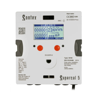
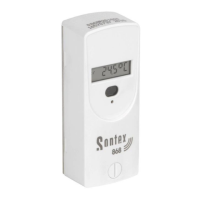
Description of the calculator's display sequence.
How to navigate menus using the control keys.
Example display showing main menu and module status.
Physical dimensions of the Supercal 5 unit.
Overview of the Supercal 5 menu structure.
Steps for commissioning and sealing the device.
Description of the main menu options.
Menu for metrological parameters and settings.
Menu for service-related functions and information.
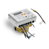
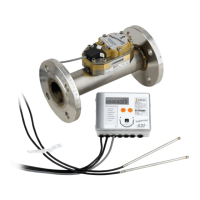
Physical dimensions of the Superstatic 440 flow sensor.
Technical specifications for the Superstatic 440 flow sensor.
Recommended horizontal mounting orientation for the sensor.
Recommended vertical mounting orientation for the sensor.
General guidelines and precautions for mounting the device.
Importance and application of security seals.
Process and concept of sealing the calculator.
How to obtain technical assistance.
Contact number for Sontex support.
Availability of the declaration of conformity document.
Manufacturer's liability and general operating conditions for the device.
Essential checks and requirements to perform before installing the device.
Using the calculator as a heat, cooling, or combined meter.
Constraint on extending the cable between sensor and calculator.
Minimum distance requirement for wiring to avoid interference.
Avoidance of radiated heat and electrical fields near the calculator.
Install calculator away from cooling pipes to prevent condensation.
Install calculator separately on the wall if vibrations are present.
Install calculator apart from flow unit for temperatures over 90°C.
Install flow sensor between two shut-off valves.
Mounting orientation of the flow sensor measuring head.
Adhering to the flow direction indicated on the sensor.
Flush pipe system before sensor installation to remove particles.
Mount flow sensor before control valve to avoid influences.
Purge pipe system during commissioning to avoid measurement errors.
Use of new and appropriate sealing materials.
Verification of water tightness for connections.
The upper part of the calculator relevant for calibration.
Matching pulse values and sensor resistance values between devices.
Ensuring equipotentiality of all grounding connections for safety.
Connection of power supply modules to the main board.
Available power supply options (battery, mains modules) for the calculator.
Electrical connection of mains power supply modules following standards.
Function and lifespan of the backup battery.
Safety precautions for handling, maintenance, and installation.
Procedure for checking leaks and operating parameters after installation.
Do not separate, extend, or shorten matched sensor pairs.
Use shielded pairs for sensor cables longer than 3m.
Use four-wire technology for unequal or long cables (>6m).
Install sensors in pockets or directly, but consistently.
Asymmetrical mounting (one direct, one with pocket) is not permitted.
Position sensor tip in the center of the pipe's cross-section.
Isolate only up to the temperature sensor screw connection.
Screw connection of sensors must not be isolated.
Details on optional communication modules and their functionality.
Use of cooling liquids and their impact on MID approval.
Description of the calculator's display sequence.
How to navigate menus using the control keys.
Example display showing main menu and module status.
Configuration of address and baud rate settings.
Setting the current date and time.
Configuration of pulse input units and factors.
Configuration for pulse input 2.
Configuration for pulse input 3.
Configuration for pulse input 4.
Configuration for pulse input 5.
Configuration for pulse input 6.
Configuration for output 1 (pulse unit and multiplier).
Configuration for output 2 (pulse unit and multiplier).
Configuration for output 3 (pulse unit and multiplier).
Configuration for output 4 (pulse unit and multiplier).
Configuration for output 5 (pulse unit and multiplier).
Configuration for output 6 (pulse unit and multiplier).
Access to the error menu and sum of error codes.
Display of cumulated energy and volume data.
Display information specific to cooling energy mode.
Display information for heating/cooling and cooling modes.
Display of cumulated input values for IN1 and IN2.
Display of cumulated input values for IN3 and IN4.
Display of cumulated input values for IN5 and IN6.
Display of temperature high/low and temperature difference.
Display of current power and flow rate.
Display of energy accumulated for day 1.
Display of energy accumulated for day 2.
Configuration of mounting position and electrical pulse value.
Display of accuracy class and nominal diameter.
Display of nominal and upper limit pressures.
Display of permanent and upper limit flow rates.
Display of lower limit flow rate and temperature range.
Display of flowmeter type and identification number.
Display of fluid type and concentration.
Display of cumulated energy with significant digits.
Display of cumulated volume with significant digits.
Display of the device's fabrication number.
Display of firmware version and CRC32 checksum.
Display of device running hours and years.
Test to verify all pixels on the display are functional.
Display of custom configurable messages.
Recommended horizontal mounting orientation for the flow sensor.
Recommended vertical mounting orientation for the flow sensor.
Mount temperature sensors symmetrically and preferably without pockets.
Asymmetrical mounting of temperature sensors is prohibited.
Do not shorten connecting cables for permanently mounted sensors.
Respect straight piping sections of 3 DN for flow meters.
Battery selection criteria for auxiliary energy and storage.
Information on measuring stability per AGFW FW 510.
Sticker requirement for customer-specific correction curves.
Manufacturer's notes on configuration and sensor head swapping.
Importance and application of security seals for tamper-proofing.
How to obtain technical assistance from Sontex.
Location to find and download the declaration of conformity.
Sontex support hotline contact information.
| Power supply | Battery (6 or 11 years), 24 V AC/DC, 230 V AC |
|---|---|
| Measuring principle | Ultrasonic |
| Nominal diameter | DN15 to DN40 |
| Communication | M-Bus, Pulse |
| Pipe Diameter Range | DN15 to DN40 |
| Outputs | Pulse |