13Installation guide | Supercal 5
EN
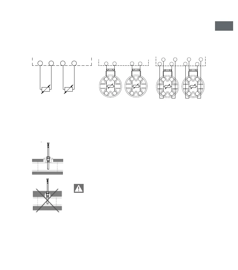
Temperature sensors connections
Wire cross section for head sensors ≥ 0,5 mm
2
(EN 1434-2)
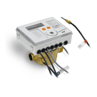
Temperature sensor installation with cooling applications
The isolation may be made only up to the temperature sensor screw
connection.
The screw connection of the temperature sensors may in no case be
isolated with. This applies even if the temperature sensor is installed
directly in the ow sensor.
1
5
2
6
r
r
w
w
3
7
4
8
r
r
w
w
1
2
rw
3
4
rw
5
67
8
r w r w
2 wires cable sensor
5/6 temperature high
7/8 temperature low
4 wires sensor with
2 wires integrator
1/2 temperature high
3/4 temperature low
4 wires sensor with
4 wires integrator
1/5 + 2/6 temperature high
3/7 + 4/8 temperature low