0449P300 Installation Superstatic 449 DE EN 19-01-2012 1 Sontex SA, 2605 Sonceboz, Schweiz, Switzerland
Einbau- und Betriebsanleitung statischer Wärmezähler Superstatic 449
Installation guidelines Static Heat Meter Superstatic 449
Allgemeines
Der statische Durchflusssensor und das Rechenwerk dürfen nur innerhalb
der auf dem Typenschild sowie in der technischen Spezifikation
aufgeführten Bedingungen betrieben werden! Bei Missachtung dieser
Vorgaben ist eine Haftung des Herstellers ausgeschlossen. Der Hersteller
haftet nicht für unsachgemäßen Einbau und Betrieb.
Plomben dürfen nicht bzw. nur durch autorisierte Personen entfernt werden,
dabei sind länderspezifische und lokale Vorschriften sowie die
Herstellerangaben zu beachten! Der Hersteller übernimmt keine
Verantwortung für die Änderung der eich- und messrelevanten Daten, falls
die werkseitige Verplombung aufgebrochen oder verletzt worden ist.
Bei der Verwendung von mehreren Wärmezählern in einer Abrechnungs-
Einheit sollten im Interesse einer möglichst gerechten Wärmeverbrauchs-
Messung gleiche Gerätearten und Einbaulagen gewählt werden.
Vor der Montage
- Auslegungsdaten der Anlagen überprüfen.
- Die Impulswertigkeit und der Einbauort des Durchflusssensors müssen
mit den auf dem Rechenwerk angegebenen Werten übereinstimmen,
Typenschilder beachten!
- Die zulässige Umgebungstemperatur beim Rechenwerk beträgt 5...55°C.
- Die Installations- und Projektierungsvorschriften sind zu beachten.
- Die Ablesbarkeit des Rechenwerkes und sämtlicher Typenschilder ist zu
beachten.
Hinweise zur richtigen Zählermontage:
Bedingungen zur Einhaltung der Richtlinie
2004/22/EG (MID) und der korrekten Einbaula-
gen siehe Seite 12
- Das Rechenwerk ist standardmäßig für den Einbau im Rücklauf
parametriert. Für den Einbau im Vorlauf ist eine spezielle Parametrierung
erforderlich, welche bei der Bestellung angegeben werden muss.
- Das Kabel zwischen dem Durchflusssensor und dem Rechenwerk darf
nicht verlängert oder verkürzt werden werden! Das Kabel ist plombiert.
General
The static flow sensor and the integrator may only be operated within the
conditions outlined on the identification plate, as well as within the technical
specification! In case of ignoring these default conditions, the manufacturer’s
responsibility is void.
The manufacturer is not liable for inappropriate installation and operation.
Seals may not be removed and/or only by authorized persons. The country-
specific, local regulations, as well as the manufacturer instructions must be
respected!
If the manufacturer’s seal has been broken or damaged, the manufacturer
cannot be made responsible for the change of the verified and measuring
relevant data.
When using several heat meters in an installation unit, one should select, in
the interest of a at most possible fair heat consumption measurement, the
same types of device and installation positions.
Before installation
- Check the design layout data of the installation.
- The pulse value and the installation location of the flow sensor must
match the values indicated on the integrator, consult the identification
plate!
- The permissible ambient temperature range of the integrator is 5 - 55 ºC.
- The installation and project prescriptions must be followed.
- The readability of the integrator and also the identification plates must be
followed.
Remarks on the correct meter installation:
Conditions to comply with the directive
2004/22/EU (MID) and correct mounting posi-
tions see page 12
- The integrator is by default parameterized for installation into the return
flow. Special parameterization is necessary for installation in the supply
flow and this must be specified with the order.
- The cable between the flow sensor and the integrator must not be ex-
tended or shorted. The cable is be sealed.
- Alle Leitungen müssen mit einem Mindestabstand von 300 mm zu
Starkstrom- und Hochfrequenzkabeln verlegt werden.
- Strahlungswärme und elektrische Störfelder in der Nähe des
Rechenwerkes sind zu vermeiden.
- Das Rechenwerk ist generell abgesetzt von der Kälteleitung zu montie-
ren.
- Es ist darauf zu achten, dass kein Kondensatwasser entlang der ange-
schlossenen Leitungen ins Rechenwerk laufen kann.
- Sofern die Gefahr von Erschütterungen im Rohrleitungssystem besteht,
sollte das Rechenwerk getrennt an der Wand montiert werden.
- Der Durchflusssensor sollte zwischen zwei Absperrventilen montiert
werden.
- Bei der Montage des Durchflusssensors muss der Messkopf seitlich
liegen (siehe Seite 12).
- Beim Durchflusssensor ist die Durchflussrichtung zu beachten (Pfeil auf
dem Durchflusssensor).
- Die Rohrleitung ist vor der Montage des Durchflusssensors zu spülen, um
zu gewährleisten, dass sich keine Fremdkörper in der Leitung befinden.
- Der Durchflusssensor soll VOR möglichen Regel-Ventilen montiert
werden um mögliche Störeinflüsse auszuschließen.
- Die Leitungen sind bei der Inbetriebnahme generell zu entlüften. Luft im
System oder im Durchflusssensor kann das Messergebnis beeinträchti-
gen.
- Verwenden Sie nur geeignetes, neues Dichtungsmaterial.
- Die Dichtigkeit der verschiedenen Anschlüsse muss überprüft werden.
- Ein Blitzschutz kann nicht gewährleistet werden; dies ist über die Hausin-
stallation sicherzustellen.
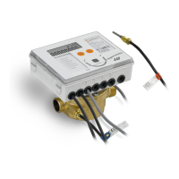
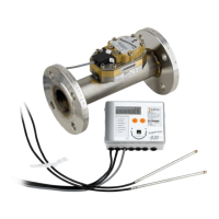
Beim statischen Wärmezähler Superstatic handelt es sich um ein Kompakt-
gerät. Es besteht aus den folgenden drei Teilgeräten:
- Schwingstrahl Durchflusssensor
- Rechenwerk Supercal
- Temperaturfühler (2- oder 4-Leitertechnik) mit oder ohne Tauchhülsen
Die Impulswertigkeit des Rechenwerks und des Durchflusssensors
sowie der Widerstand der Temperaturfühler und Rechenwerk müssen
aufeinander abgestimmt sein. Etiketten der Geräte vergleichen!
- All wiring must be installed with a minimum distance of 300 mm from
heavy voltage and high frequency cables.
- Radiated heat and interfering electrical fields close to the integrator must
be avoided.
- In general, the integrator should be installed away from the cooling pipes.
- It has to be ensured that no condensed water can run along the wires into
the calculator.
- If the danger of vibrations in the piping system exists, the integrator should
be installed separately on the wall.
- The flow sensor should be installed between two shut-off valves.
- The flow sensor must be mounted with the measuring head to the side
(see page 12).
- The flow direction of the flow sensor must be respected (arrow on the flow
sensor).
- Flush the pipe system before installing the flow sensors to guarantee that
no foreign particles remain in the pipe.
- The flow sensor shall be mounted BEFORE any control valve to
exclude any potential parasitic influences.
- During commissioning the pipe system must be purged. Air in the system
of the flow sensor may affect the measurement..
- Use only new and appropriate sealing material.
- Water tightness of the different connections should be verified.
- A lightning protection cannot be ensured; this protection has to be guaran-
teed by the house installation.
The static heat meter Superstatic is a compact unit and consists of the fol-
lowing three partial units:
- Fluid oscillator of flow sensor
- Integrator
- Temperature sensors (2- or 4-wire) with or without pockets
The pulse values of the integrator and of the flow unit, as well as the
resistance value of the temperature sensors and the integrator are
matched one to the other. Compare the labels of the Devices!