8 Installation guide | Supercal 5
During commissioning the pipe system must be purged. Air in the system of
the ow sensor may affect the measurement.
Use only new and appropriate sealing material.
Water tightness of the different connections should be veried.
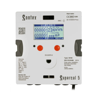
The Supercal 5 is a compact calculator and consists of the following two partial
units:
Measuring and calibrating-relevant upper part
Lower part
The pulse values of the calculator and of the ow unit, as well as the resistance
value of the temperature sensors (Pt500) must match. Compare the labels of the
devices!
Terminal connection type
5, 6 2-wire direct connection, temperature high
1, 2 and 5, 6 4-wire, temperature high
7, 8 2-wire direct connection, temperature low
3, 4 and 7, 8 4-wire, temperature low
10 (+) pulse inputs ow sensor 440 (white cable)
11 (-) pulse inputs ow sensor 440 (green cable)
9 Power supply of the ow sensor 440 (brown cable)
50 (+) Pulse input, additional pulse input 1
51 (-) Pulse input, additional pulse input 1
52 (+) Pulse input, additional pulse input 2
53 (-) Pulse input, additional pulse input 2
16 (+) Open collector-output 1
17 (-) Open collector output 1 + 2
18 (+) Open collector output 2
24 M-Bus
25 M-Bus
Cable connection
To connect the inputs and outputs the calculator’s upper part must be removed.
Shielded cables must be grounded with a strain relief!