Do you have a question about the Sony BRC-H700 and is the answer not in the manual?
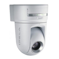
Combines Pan/Tilt/Zoom capabilities with stylish and unobtrusive design for versatile use.
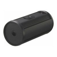
Offers a cost-effective solution for remote video shooting applications with advanced features.
Enables long-distance transmission of uncompressed digital data via optical fiber cable.
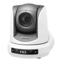
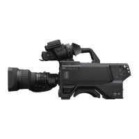
Details the BRC-H700 camera's basic connection for a simple system.
Illustrates the system configuration for BRC-H700 and BRU-H700 using an optical multiplex unit.
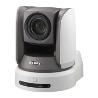
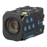
Outlines the BRC-Z700 camera's basic connection for a simple system setup.
Shows the system configuration for BRC-Z700 and BRU-H700 with an optical multiplex unit.
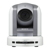
Describes the basic system setup for the BRC-300/300P camera.
Details the system configuration for BRC-300/300P and BRU-300/300P units.
Explains how to configure a daisy-chain system with multiple cameras.
Details the location and function of parts for BRC-H700, BRC-Z700, and BRC-300/300P cameras.
Explains the location and function of BRU-H700 and BRU-300/300P optical multiplex units.
Details the location and function of various optical multiplex cards and optional video cards.
Describes the basic connections for cameras and monitors.
Provides guidance on setting up the monitor for camera adjustment.
Explains the location and function of the IR Remote Commander Unit's controls.
Details the features and capabilities of the RM-BR300 Remote Control Unit.
Explains how to control cameras using the AWS-G500/G500HD Anycast Station.
Explains color adjustment techniques for BRC-H700 and BRC-Z700 cameras.
Details the color detail adjustment feature for BRC-Z700.
Provides estimated viewing angle charts for BRC series cameras.
Describes how to match output signal timing using Sync Master.
Specifies recommended lighting levels for BRC series cameras.
Provides instructions for using the VISCA RS-422 connector plug.
Illustrates the wiring diagram for VISCA RS-422 connections.
Summarizes information on CCFC cables for optical fiber connections.
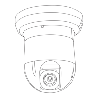
Provides an example of installing the camera on a ceiling, including steps and cautions.
Illustrates how to install the camera on a shelf or similar surface in a high position.
| Camera Type | PTZ Camera |
|---|---|
| Digital Zoom | 12x |
| Horizontal Resolution | 1000 TV lines |
| Pan Angle | ±170° |
| Sensor Type | CMOS |
| Operating Temperature | 0°C to 40°C (32°F to 104°F) |
| Storage Temperature | -20°C to +60°C (-4°F to +140°F) |
| Video Output | HD-SDI, HDMI |
| Network Protocol | HTTP, RTSP, RTP |
| Power Supply | AC 100 V to 240 V, 50 Hz/60 Hz |
| Tilt Angle | -30° to +90° |
| Control Interface | RS-232C, RS-422 |
| Signal System | 1080i/60, 1080i/50, 720p/60, 720p/50, 480i/60, 576i/50 |
| Pan/Tilt Range | Pan: ±170°, Tilt: -30° to +90° |
| Power Requirements | AC 100 V to 240 V, 50 Hz/60 Hz |