Do you have a question about the Sony BRC SERIES and is the answer not in the manual?
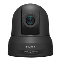
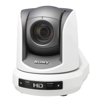
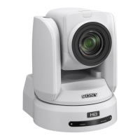
Describes the integrated P/T/Z functionality and compact design of BRC series cameras.
Highlights the discreet design suitable for capturing natural expressions in live event settings.
Discusses the affordability and value proposition of BRC series cameras.
Explains the capability for long-distance data transmission using optical fiber.
Details the various video signal outputs achievable with optional cards for system flexibility.
Covers controlling multiple cameras simultaneously using various remote units.
Presents other notable features like flexible installation and multiple presets.
Details the location and function of various parts for BRC series cameras.
Explains the rear and bottom parts of the BRC-H900 camera.
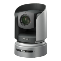
Details the rear and bottom parts of the BRC-H700 camera.
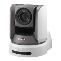
Explains the rear and bottom parts of the BRC-Z700 camera.
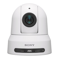
Details the rear and bottom parts of the BRC-Z330 camera.
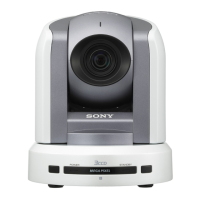
Explains the rear and bottom parts of the BRC-300/300P camera.
Provides information on the location and function of Optical Multiplex Units.
Details the parts and connections of the BRU-SF10 unit.
Explains the parts and connections of the BRU-H700 unit.
Details the parts and connections of the BRU-300/300P unit.
Information on optical multiplex and optional video cards.
Details the BRBK-H700 HD Optical Multiplex Card's audio and optical connectors.
Explains the HFBK-HD1 interface board's monitor and HD-SDI connectors.
Details the HFBK-SD1 interface board's monitor and video/SD-SDI connectors.
Explains the HFBK-XG1 interface board's monitor connector.
Details the HFBK-TS1 interface board's audio and i.LINK connectors.
Explains the BRBK-MF1 card's audio input and optical connectors.
Details the BRBK-HSD1 card's SDI output and HD/SD select switch.
Explains the BRBK-HD2 card's SDI output connector.
Details the BRBK-303 card's optical connector.
Explains the BRBK-301 card's RGB/SYNC connector.
Details the BRBK-302 card's SDI connector.
Explains the BRBK-304 card's i.LINK (DV) OUT connector.
Details the BRBK-HSD2 card's SDI output and panel switch.
Explains the BRBK-SA1 card's video, S-video, and RGB/SYNC connectors.
Information on the location and function of IP control cards.
Details the BRBK-IP10 card's LAN, Reset, SDI connectors and HD/SD switch.
Explains the BRBK-IP7Z card's LAN, Reset, SDI connectors and HD/SD switch.
Illustrates basic connections for cameras and monitors.
Provides guidance on setting up monitors for camera adjustment.
Details the buttons and functions of the IR remote commander.
Describes the features and capabilities of the RM-BR300 remote control unit.
Explains how to store camera settings using the memory preset feature.
Describes how to set the speed for camera movement to preset positions.
Lists the necessary equipment for operating with the RM-IP10 controller.
Illustrates the system configuration for IP control with the RM-IP10.
Shows the system configuration for controlling BRC cameras with the BRS-200.
Explains the different operating modes of the BRS-200 switcher.
Provides wiring diagrams for connecting BRC cameras to the BRS-200 via RS-422.
Details how to control BRC cameras using the AWS-G500 Anycast Station.
Explains camera control using the VISCA protocol with the AWS-G500.
Describes how to operate PGM/NEXT buttons from the RM-BR300 with AWS-G500.
Explains how to adjust specific color regions without affecting white balance.
Details image enhancer adjustments for colors, including skin tone.
Describes the Color AE function for adjusting exposure based on specific colors.
Explains the KNEE and GAMMA adjustment options available on the camera menu.
Details the Sync Master setting for matching output signal timing.
Describes various audio signal mixing and output configurations.
Shows priority settings between BRC cameras and BRU units.
Provides instructions for using the VISCA RS-422 connector plug.
Introduces wiring diagrams for VISCA RS-422 connections.
Wiring diagram for VISCA RS-422 connection between RM-BR300/RM-IP10 and cameras.
Wiring diagram for VISCA RS-422 connection between BRS-200 and cameras.
Step-by-step guide for installing the camera on a ceiling.
Instructions for installing the camera on a shelf or similar surface.
| Category | PTZ Camera |
|---|---|
| Sensor Type | CMOS |
| Pan/Tilt Range | Pan: ±170 degrees, Tilt: +90 degrees to -30 degrees |
| Output | HDMI, IP |
| Remote Control | VISCA over IP, Serial VISCA |
| Operating Temperature | 0°C to 40°C (32°F to 104°F) |