8
Back
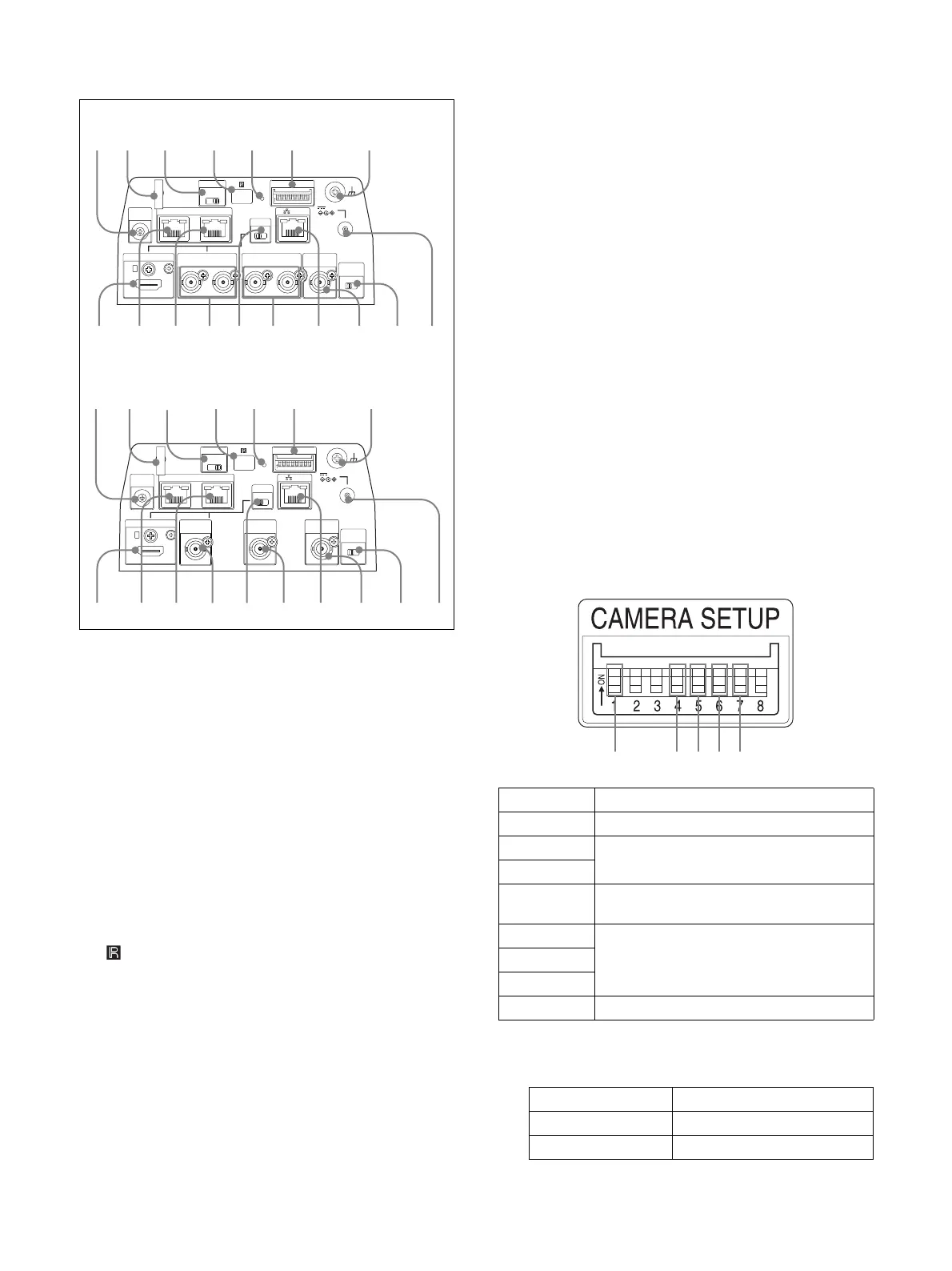
H SYSTEM SELECT switch
Used for selecting the video format of the signal to
be output from the HDMI OUT, MONITOR OUT,
and LINE OUT terminals.
For details, see “SYSTEM SELECT switch
settings” (page 64).
I AC adapter cord clamper
Fix the cord of an AC adapter with the cord clamper
so that it does not come out.
J IR SELECT switch
Select the camera number when you operate
multiple cameras with the same remote commander.
K Remote commander sensors
These are sensors for the supplied remote
commander.
L Network reset switch
This switch is for initializing network settings such
as the IP address.
Press the switch for 5 seconds or longer with a pen
point, etc., to initialize the network settings.
The camera will reboot, and the network settings
will return to the factory default.
Factory settings for network
Network settings
IP address: 192.168.0.100
Subnet mask: 255.255.255.0
Default gateway: 0.0.0.0
CNS tab (page 51)
Mode: Bridge
Master IP: 0.0.0.0
Camera No.: 1
Tracking data output tab (page 51)
Enable: Off
Destination IP address: (blank)
UDP port number: 40000
Transfer mode: Always
Camera ID: 255
General
Camera name: CAM1
User name: admin
*
Password: Admin_1234
* The user name cannot be changed.
M CAMERA SETUP switches
SDI format/level settings
The baud rate settings and camera address settings
of RS-422 are set for VISCA communication.
CAMERA SETUP switch settings
1 SDI format/level settings
This setting is enabled when the signal format is
1920×1080/50p or 1920×1080/59.94p.
EXT SYNC IN
TERMI-
NATION
ON OFF
ON
ON
OFF
LINE OUT
SDI 1
OSD
LAN
SDI 2
23456781
MONITOR OUTHDMI OUT
SDI 1 SDI 2
IN
SYSTEM
SELECT
IR SELECT
CAMERA SETUP
123
VISCA RS - 422 OUT
12V
qd qf
g
h
j
;
a
s
d
f
l
k
98 0 qa qs
EXT SYNC IN
TERMI-
NATION
ON OFF
ON
ON
OFF
OSD
LAN
23456781
HDMI OUT
IN
SYSTEM
SELECT
IR SELECT
CAMERA SETUP
123
VISCA RS - 422 OUT
12V
MONITOR
OUT
LINE OUT
qd qf
g
h
j
;
a
s
d
f
l
k
98 0 qa qs
BRC-X1000
BRC-H800
Switch No. Setting items
1 Setting up 3G-SDI level
2 System reserve
3
4 Baud Rate settings of RS-422 for VISCA
communication
5 VISCA Address settings for VISCA
communication
6
7
8 System reserve
Switch state SDI format/level
ON Level-B
OFF Level-A
1456 7




 To Next Page