L,
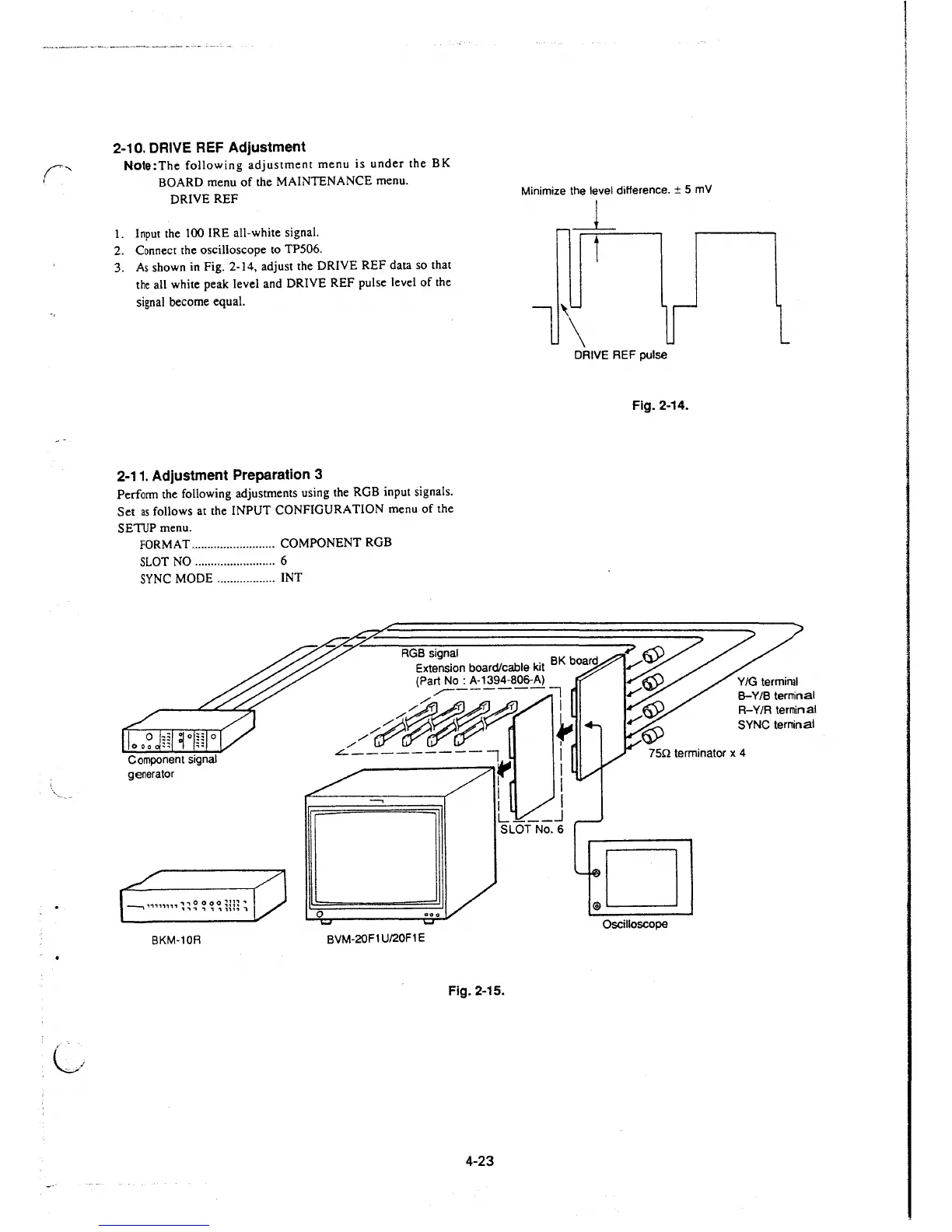
2-10. DRIVE REF Adjustment
Note:The following adjustment menu is under the BK
BOARD menu of the MAINTENANCE menu.
DRIVE REF
Minimize the level difference. ± 5 mV
1. Input the 100 IRE all-white signal.
2. Connect the oscilloscope to TP506.
3. As shown in Fig. 2-14, adjust the DRIVE REF data so that
the all white peak level and DRIVE REF pulse level of the
signal become equal.
_L
i
DRIVE REF pulse
2-11. Adjustment Preparation 3
Perform the following adjustments using the RGB input signals.
Set
as follows at the INPUT CONFIGURATION menu of the
SETUP menu.
FORMAT .......................... COMPONENT RGB
SLOT NO .........................
6
SYNC MODE .................. INT
RGB signal
Extension board/cable kit
BK boa
rd
(Part No: A-1394-806-A)
,,,--------:1
/#~~~
~
Fig. 2-14.
8-Y/B terminal
R-Y/R terminal
SYNC teminal
Component signal
generator
..:::.---------, I
75n terminator x 4
--, ,.,.,,,,,,,., o o o o
~n~
,
, ., ., "I ., , ,,,, i
BKM-10R
0
BVM-20F1 U/20F1 E
r I
I I
1 I
L ___ J
SLOT No. 6
Oscilloscope
Fig. 2-15.
4-23
 Loading...


