2-12. RGB Signal SETUP Adjustment
Note: The following adjustment menus are under the BK
BOARD menu of the MAINTENANCE menu.
R SETUP
G SETUP
B SETUP
I. Input 100 IRE RGB signal.
2. Connect the oscilloscope to TPI04.
3. Adjust the R SETUP data so that the black level and setup
signal level become equal.
4. Connect the oscilloscope to TP304.
5. Adjust the G SETUP data
so that the black signal level and
setup signal level become equal.
6. Connect the oscilloscope to TP504.
7. Adjust the B SETUP data so that the black signal level and
setup signal level become equal.
Equalize
~
Fig. 2-16.
2-13. RGB Signal 100 IRE Adjustment
Note:The following adjustment menus are under the BK
BOARD menu of the MAINTENANCE menu.
R 100 IRE
G 100 IRE
B 100 IRE
I. Input the 100 IRE RGB signal.
2. Connect the oscilloscope to TP104.
3. Adjust the R 100 IRE data so that the 100 IRE level and
1 ()() IRE pulse level of the signal become equal.
4. Connect the oscilloscope to TP304.
5. Adjust the G 100 IRE data so that the 100 IRE level and
1 ()() IRE pulse level of the signal become equal.
6. Connect the oscilloscope to TP504.
7. Adjust the B 100 IRE data so that the 100 IRE level and
100 IRE pulse level of the signal become equal.
Equalize
~,..........---,
Fig. 2-17.
4-24
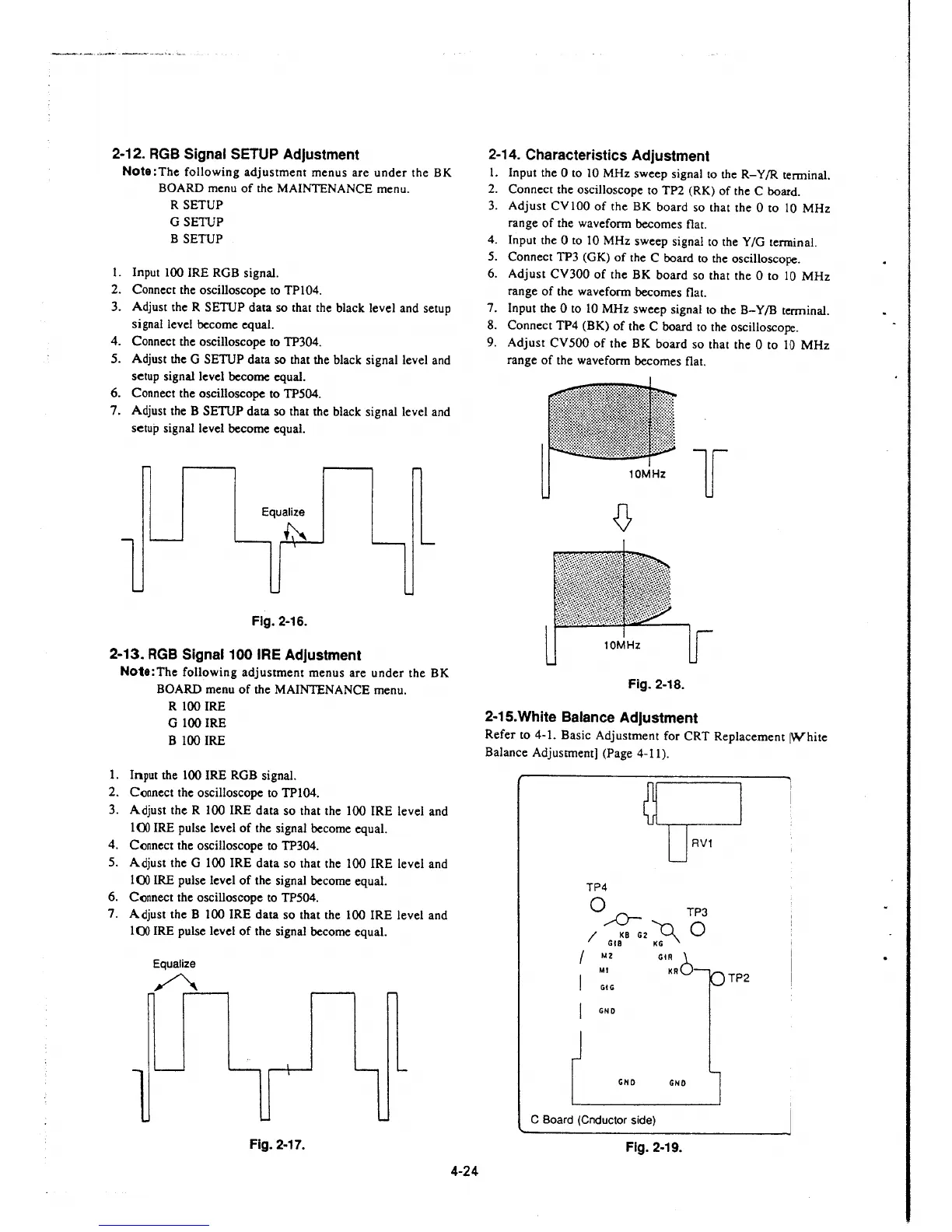
2-14. Characteristics Adjustment
1. Input the O to 10 MHz sweep signal to the R- Y /R terminal.
2. Connect the oscilloscope to TP2 (RK) of the C board.
3. Adjust CVIOO of the BK board so that the Oto
10 MHz
range of the waveform becomes flat.
4. Input the O to IO MHz sweep signal to the Y /G tenninal.
5. Connect TP3 (GK) of the C board to the oscilloscope.
6. Adjust CV300 of the BK board so that the Oto 10 MHz
range of the waveform becomes flat.
7. Input the Oto 10 MHz sweep signal to the B-Y/B terminal.
8. Connect TP4 (BK) of the C board to the oscilloscope.
9. Adjust CV500 of the BK board so that the O to 10 MHz
range of the waveform becomes flat.
10MHz
l
Fig. 2-18.
2-15.White Balance Adjustment
Refer to 4-1. Basic Adjustment for CRT Replacement [White
Balance Adjustment] (Page 4-11).
TP4
Q ,.-0- TP3
/ KB G2
~
0
GIB KG
/ M2
Ml
I GIG
GiR 1.
KRO
GNO
GNO GNO
C Board (Cnductor side)
Fig. 2-19.
TP2
 Loading...


