3. BC Board Adjustment
3-1. Adjust Preparation
Set !CH as follows using INPUT CONFIGURATION menu of SETUP menu.
FORMAT .......................... COMPONENT YUY SMPTE/EBU N-10
SLOT NO ......................... 6
SYNC MODE .................. INT
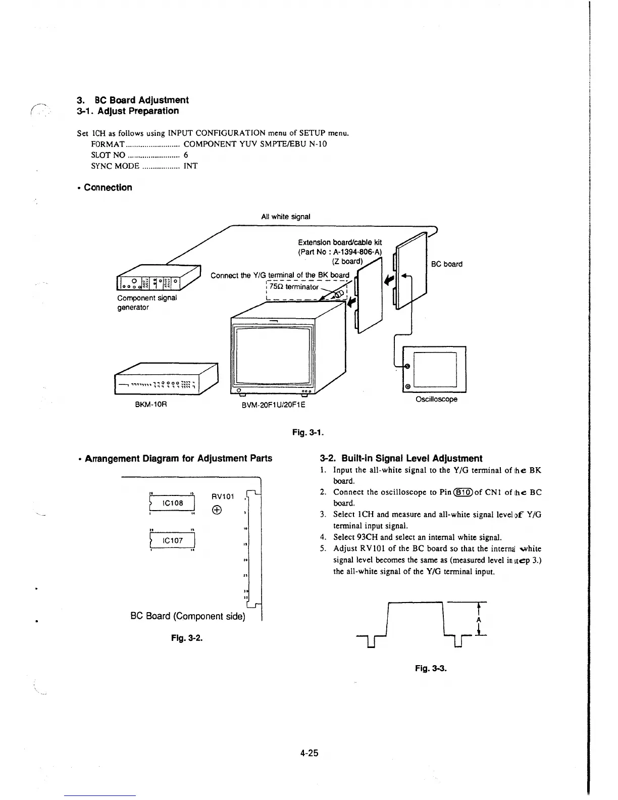
• Connection
Component signal
generator
0
All white signal
Extension board/cable kit
(Part No: A-1394-806-A)
(Z board)
.D
BKM-10R
BVM-20F1 U/20F1 E
Oscilloscope
• Arrangement Diagram for Adjustment Parts
..
"
RV101
~
IC108
I
(±)
I
..
..
"
~
IC107
.J
..
BC Board (Component side)
Fig. 3-2.
Fig. 3-1.
4-25
3-2. Built-in Signal Level Adjustment
1. Input the all-white signal to the Y /G terminal of the BK
board.
2. Connect the oscilloscope to Pin@IQ)of CNI of the BC
board.
3. Select ICH and measure and all-white signal level of Y/G
terminal input signal.
4. Select 93CH and select an internal white signal.
5. Adjust RV IO I of the BC board so that the
internaJ 'Ylhite
signal level becomes the same as (measured level in 1tep 3.)
the all-white signal of the Y/G terminal input.
t
A
j_
Fig. 3-3.
 Loading...


