....
I
....
0)
gAffina thA lnc,ut Confiauration - INPUT CONJ:'IGURATION M@nu
l~Mitill~-;j
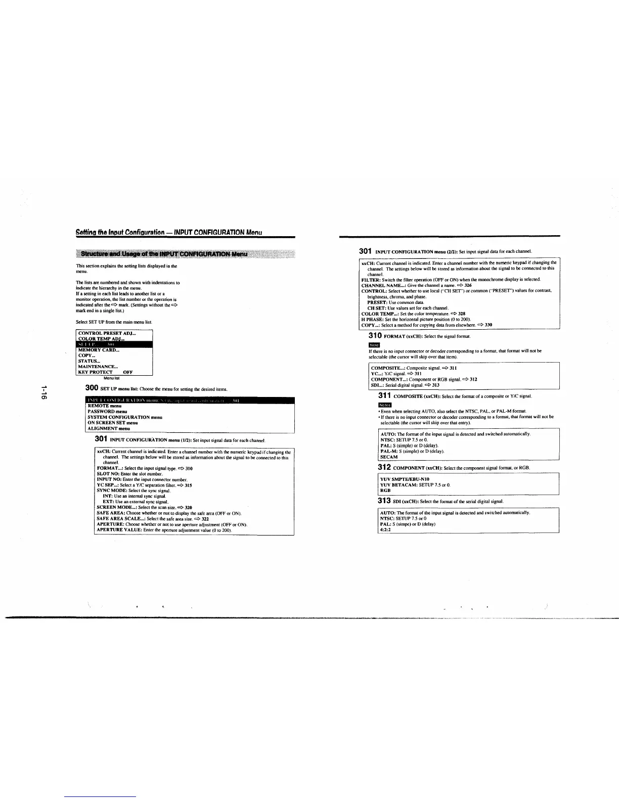
This section explains the setting lists displayed in the
menu.
The lists are numbered and shown with indentations to
indicate the hierarchy in the menu.
If a setting in each list leads to another list or a
monitor operation, the list number or the operation is
indicated after
the~ mark. (Settings without the
~
mark end in a single list.)
Select SET UP from the main menu list.
CONTROL PRESET ADJ ...
COLOR TEMI' ,\l.)J~.
MEMORY CARD ...
COPY ...
STATUS ...
MAINTENANCE ...
KEY PROTECT OFF
Menu list
300 SET UP menu list: Choose the menu for setting the desired items .
REMOTE menu
PASSWORD menu
SYSTEM CONFIGURATION menu
ON SCREEN SET menu
ALIGNMENT menu
301 INPUT CONFIGURATION menu (1/2): Set input signal data for each channel.
xx CH: Current channel is indicated. Enter a channel number with the numeric keypad if changing the
channel. The settings below will be stored as information about the signal to be connected to this
channel.
FORMAT ... : Select the input signal type.~ 310
SLOT NO:
Enter the slot number.
INPUT NO: Enter the input connector number.
YC SEP ... : Select a Y/C separation filter.~ 315
SYNC MODE:
Select the sync signal.
INT: Use an internal sync signal.
EXT: Use an external sync signal.
SCREEN MODE ... : Select the scan size.~ 320
SAFE AREA:
Choose whether or not to display the safe area (OFF or ON).
SAFE AREA SCALE ... : Select the safe area size.
~
322
APERTURE:
Choose whether or not to use aperture adjustment (OFF or ON).
APERTURE VALUE: Enter the aperture adjustment value (0 to 200).
301 INPUT CONFIGURATION menu (2/2): Set input signal data for each channel.
xxCH: Current channel is indicated. Enter a channel number with the numeric keypad if changing the
channel. The settings below will be stored as information about the signal to be connected to this
channel.
FILTER: Switch the filler operation (OFF or ON) when the monochrome display is selected.
CHANNEL NAME ... : Give the channel a name.
~
3U
CONTROL: Select whether to use local ("CH SEf") or common (""PRESET') values for contrast,
brightness. chroma, and phase.
PRESET: Use common data.
CH SET: Use values set for each channel.
COLOR TEMP ... : Set the color temperature.
~
328
H PHASE:
Set the horizontal picture position (0 to 200).
COPY ... : Select a method for copying data from elsewhere.
~
330
31 0 FORMAT (xxCH): Select the signal format.
mm
If there is no input connector or decoder corresponding to a format, that format will not be
selectable (the cursor will skip over that item).
COMPOSITE ... : Composite signal.
~
311
YC ... :
Y/C signal.~ 3J1
COMPONENT ... : Component or RGB signal.~ 312
SDI ... : Serial digital signal.~ 313
311 COMPOSITE (xxCH): Select the format of a composite or Y IC signal.
mmn
• Even when selecting AUTO, also select the NTSC, PAL, or PAL-M format.
• If there is no input connector or decoder corresponding to a formal, that format will not be
selectable (the cursor will skip over that
entry).
AUTO: The formal of the input signal is detected and switched automatically.
NTSC: SETUP 7.5 or 0.
PAL: S (simple) or D (delay).
PAL-M: S (simple) or D (delay).
SECAM
312 COMPONENT (xxCH): Select the component signal format, or RGB.
YUV SMPTE/EBU-N10
YUV BETA CAM: SETUP 7.5 or 0.
RGB
313 SDI (xxCH): Select the format of the serial digital signal.
AUTO: The format of the input signal is detected and switched automatically.
NTSC: SETUP 7.5 or 0
PAL: S (simpe) or D (delay)
4:2:2
-------------------------------------------------------------,·-~·---------·"·•·•-,•--,,~-··~-"~.,
 Loading...


