......
I
"'
......
Setting the Channel Selection Method and Power-Up Conditions - SYSTEM
CONFIGURATION Menu
This section explains the setting lists displayed in the
menu.
The lists are numbered and shown with indentations to
indicate the hierarchy in the menu.
If a setting in each list leads to another list or a
monitor operation, the list number or the operation is
indicated after the c¢ mark. (Settings without the c¢
mark end in a single list.)
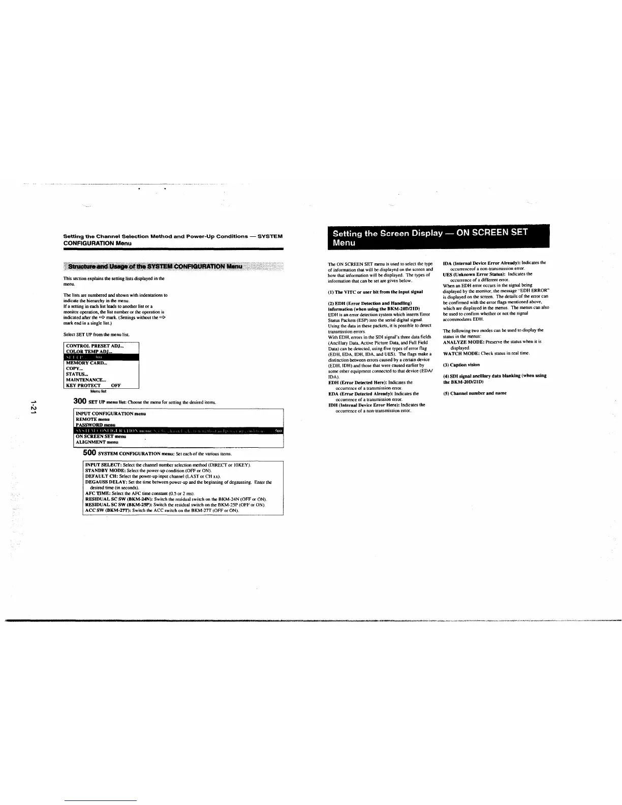
Select SET UP from the menu list.
CONTROL PRESET ADJ ...
COL.OR TEMf AW-,._
MEMORY CARD ...
COPY ...
STATUS ...
MAINTENANCE. ..
KEY PROTECT OFF
Menu6st
300 SET UP menu list: Choose the menu for setting the desired items.
INPUT CONFIGURATION menu
REMOTE menu
PASSWORD menu
ON SCREEN SET menu
ALIGNMENT menu
500 SYSTEM CONFIGURATION menu: Set each of the various items.
INPUT SELECT: Select the channel number selection method (DIRECT or IOKEY).
STANDBY MODE: Select the power-up condition (OFF or ON).
DEFAULT CH: Select the power-up input channel (LAST or CH xx).
DEGAUSS DELAY: Set the time between power-up and the beginning of degaussing. Enter the
desired time (in seconds).
AFC T.IME: Select the AFC time constant (0.5 or 2 ms).
RESIDUAL SC SW (BKM-24N): Switch the residual switch on the BKM-24N (OFF or ON).
RESIDUAL SC SW (BKM-2SP): Switch the residual switch on the BKM-25P (OFF or ON).
ACC SW (BKM-27T): Switch the ACC switch on the BKM-27T (OFF or ON).
Setting the Screen Display - ON SCREEN SET
Menu
The ON SCREEN SET menu is used to select the type
of information that will be displayed on the screen and
how that information will be displayed. The types of
information that can be set are given below.
(t) The VITC or user bit from the input signal
(2) EDH (Error Detection and Handling)
Information (when using the BKM-20D/21D)
EDH is an error detection system which inserts Error
Status Packets (ESP) into the serial digital signal.
Using the data in these packets. it is possible to detect
transmission errors.
With EDH, errors in the SDI signal's three data fields
(Ancillary Data, Active Picture Data, and Full Field
Data) can be detected, using five types of error flag
(EDH, EDA, IDH, IDA, and UES). The flags make a
distinction between errors caused by a certain device
(EDH, IDH) and those that were caused earlier by
some other equipment connected to that device (EDA/
IDA).
EDH (Error Detected Here): Indicates the
occurrence of a transmission error.
EDA (Error Detected Already):
Indicates the
occurrence of a transmission error.
IDH (Internal Device Error Here): Indicates the
occurrence of a non-transmission error.
IDA (Internal Device Error Already): Indicates the
occurrenceof a non-transmission error.
UES (Unknown Error Status): Indicates the
occurrence of a different error.
When an EDH error occurs in the signal being
displayed by the monitor, the message
··EDH ERROR"
is displayed on the screen. The details of the error can
be confirmed with the error flags mentioned above,
which are displayed in the menus. The menus can also
be used to confirm whether or not the signaJ
accommodates EDH.
The following two modes can be used to display the
status in the menus:
ANALYZE MODE:
Preserve the status when it is
displayed.
WATCH MODE: Check status in real time.
(3) Caption vision
(4) SDI signal anclllary data blanking (when using
the BKM-20D/21D)
(5) Channel number and name
 Loading...


