(
l
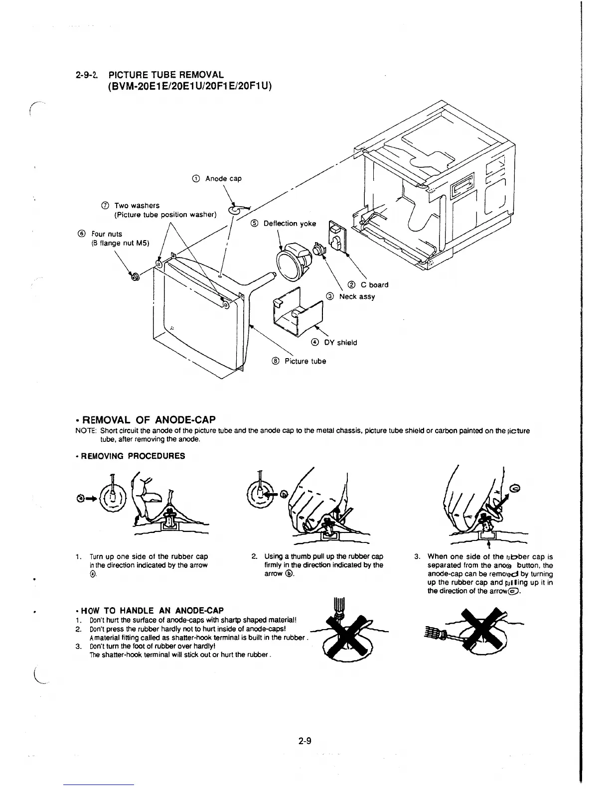
2-9-2. PICTURE TUBE REMOVAL
(BVM-20E1 E/20E1 U/20F1 E/20F1 U)
CD
(J) Two washers
(Picture tube position washer)
® Four nuts
(B flange nut MS)
~
• REMOVAL OF ANODE-CAP
@ C board
® Picture tube
NOTE: Short circuit the anode of the picture tube and
the anode cap to the metal chassis, picture tube shield or carbon painted on the picture
tube, after removing the anode.
• REMOVING PROCEDURES
1. Turn up one side of the rubber cap
in the direction indicated by the arrow
©.
• HOW TO HANDLE AN ANODE-CAP
2. Using a thumb pull up the rubber cap
firmly in the direction indicated by the
arrow@.
1. Don't hurt the surface of anode-caps with shartp shaped material!
2. Don't press the rubber hardly not to hurt inside of anode-caps!
A material fitting called as shatter-hook terminal is built in the rubber .
3. Don't turn the foot of rubber over hardly!
The shatter-hook terminal will stick out or hurt the rubber.
2-9
3. When one side of the rubber cap is
separated from the
an~e button, the
anode-cap can be
remo'ed by turning
up the rubber cap and
M ling up it in
the direction of the
arrow@.
 Loading...


