7. Set the color of the screen to green only (Turn on the
SHITT button (LED lights up in orange), and turn on the R
button or B button (LED lights up).)
8. Rotate the Purity knob, and adjust so that the green comes
to the center of the screen as shown in Fig. 1-4.
R
G
8
Flg.1-4.
9.
Move DY backwards, and adjust so that the color of the
whole screen becomes green only.
10. Adjust the tilt of DYat cross hatch signal and tighten the
screw of DY.
11. Secure the deflection york with four (20 Inch), three
(l4
Inch) spacers.
Fig. 1-5.
• Final check
After adjusting, check that there is no mislanding when the unit
is
faced in all four directions, nonh, south, east, west.
4-3
[H Blanking Adjustment]
• Preparations
1. Connect the signal generator and input the monoscope
signal.
2. Increase BRIGHT until the blanking can
be seen.
Note:The following adjustment menus are under the E
BOARD menu of the MAINTENANCE menu.
H BLK
WIDTII
H BLKPHASE
H CENTER
H PHASE
H SIZE
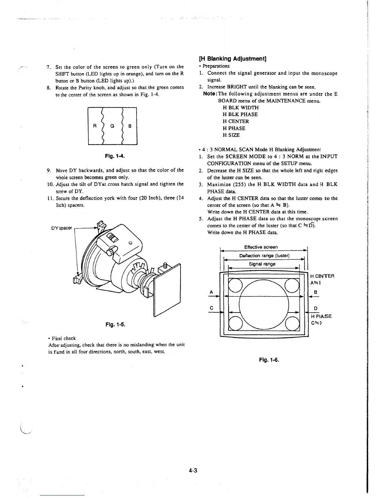
• 4 : 3 NORMAL SCAN Mode H Blanking Adjustment
1. Set the SCREEN MODE to
4 : 3 NORM at the INPUT
CONFIGURATION menu of the SETUP menu.
2. Decrease the H SIZE so that the whole left and right edges
of the luster can be seen.
3. Maximize (255) the H BLK WIDTH data and H BLK
PHASE data.
4. Adjust the H CENTER data so that the luster comes to the
center of the screen (so that A
~
B).
Write down the H CENTER data at this time.
5. Adjust the H PHASE data so that the monoscopc screen
comes to the center of the luster (so that C
~I)).
Write down the H PHASE data.
Effective screen
Deflection range (luster)
Signal range
Fig.1-6.
H CENTER
A!::;B
B
C!:;D
 Loading...


