[Linearity Adjustment]
Note:The following adjustment menus are under the E
BOARD menu of the MAINTENANCE menu.
H PHASE
V CENTER
H LIN BAL
HLIN
V LIN BAL
V LIN AMP
H KEY BAL
HKEY
H PIN BAL
H PIN
H CENTER PIN
H MID PIN
H CORNER PIN
1. Input the cross hatch signal.
2. Check that the image is not tilting, and there is no top and
bottom PIN distortion nor horizontal trapezoid distortion.
Tilt : Adjust the DY tilt.
Top/bottom Pin distortion : Adjust the top and bottom
DY head swing
Horizontal trapezoid distortion : Adjust using the DY
TL V VR (take note that
the convergence may
be
disrupted.)
3. Input the monoscope signal.
4. Set the SCREEN MODE to 4 : 3 NORM at the INPUT
CONFIGURATION menu.
5. Adjust the H PHASE data, and adjust the horizontal center
of the image.
6. Adjust the vertical center of the image.
7. Input the cross hatch signal.
8.
A,.djust the V SIZE. V LIN BAL, and V LIN data as shown
in Fig. 1-9.
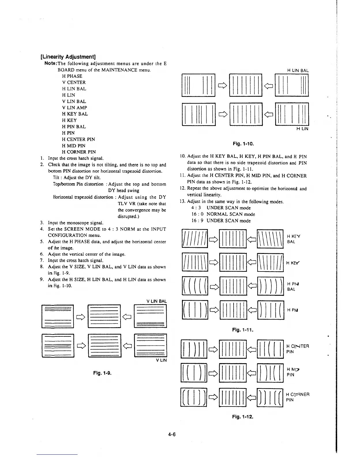
9. Adjust the H SIZE, H LIN BAL, and H LIN data as shown
in Fig. 1-10.
Fig. 1-9.
4-6
Flg.1-10.
10. Adjust the H KEY BAL, H KEY, H PIN BAL, and H PIN
data so that there is no side trapezoid distortion and PIN
distortion as shown in Fig. 1-11.
11. Adjust the H CENTER PIN, H MID PIN, and H CORNER
PIN data as shown in Fig. 1-12.
12. Repeat the above adjustment to optimize the horizontal and
vertical linearity.
13. Adjust in the same way in the following modes.
4 : 3 UNDER SCAN mode
16: 0 NORMAL SCAN mode
16 : 9 UNDER SCAN mode
RQillIIIillQ. ~A:E~
m Q [Ill[illo[illllll] H KEY
[ill] Q[Ill[illo[ill] ~Jc"
[IJ]Q[[[[ill]omITIJ HP~
Fig. 1-11.
[JJ]] Q[Ill[illo[ill]] ~
1
~ENTEA
[D]QillII(illo[ill]J ~,~o
[[DJ] Q[Ill[illomITIJ ~l~~NEA
Fig.1-12.
 Loading...


