{Convergence Adjustment]
• Preparation
1. Set the SCREEN MODE to 4:3 NORM at the INPUT
CONFIGURATION menu.
2. Input the cross hatch signal.
3. Check that the H ST AT data is the center value (128).
Note:The H STAT adjustment menu is under the
E BOARD
menu of the MAINTENANCE menu.
4. For the 14 inch model, set the 4-pole magnet of the DY to
the OFFSET state.
5. For the 20 inch model, set the 6-pole magnet of the DY to
the OFFSET state.
60°
\~/
Set the 6-pole magnet of the
DY to the OFFSET state.
~--- Align projections
to each other.
Fig. 1-13.
4-7
[Static Convergence Adjustment]
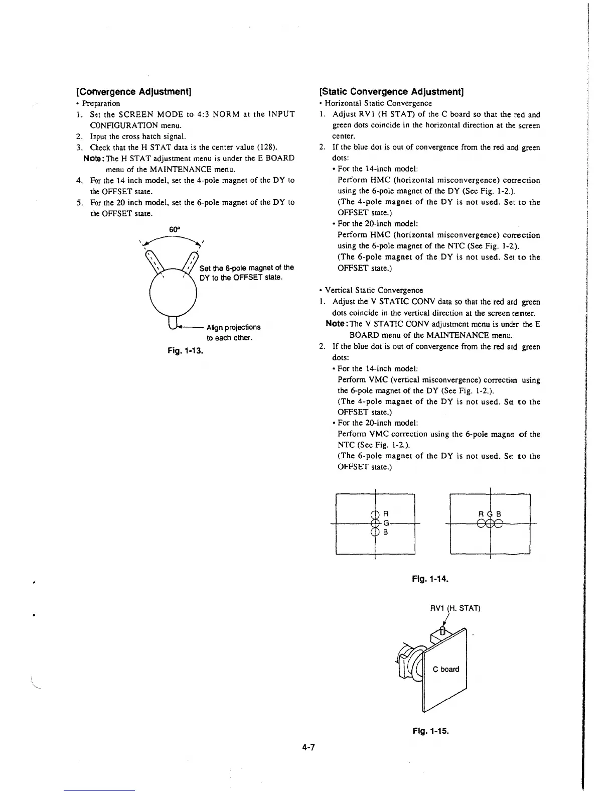
• Horizontal Static Convergence
I. Adjust RV 1 (H ST AT) of the C board so that the red and
green dots coincide in the horizontal direction at the screen
center.
2.
If the blue dot is out of convergence from the red and green
dots:
• For the 14-inch model:
Perform HMC (horizontal misconvergence) correction
using the 6-pole magnet of the DY (See Fig. 1-2.).
(The 4-pole magnet of the DY is not used. Set to the
OFFSET state.)
• For the 20-inch model:
Perform HMC (horizontal misconvergence) correction
using the 6-pole magnet of the NTC (See Fig. 1-2.).
(The 6-pole magnet of the DY is not used. Set to the
OFFSET state.)
• Venical Static Convergence
1. Adjust the V STATIC CONY data so that the red
a~d green
dots coincide in the venical direction at the screen center.
Note: The V ST A TIC CONY adjustment menu is under the E
BOARD menu of the MAINTENANCE menu.
2.
If the blue dot is out of convergence from the red and green
dots:
• For the 14-inch model:
Perform VMC (vertical misconvergence)
correctfon using
the 6-pole magnet of the DY (See Fig. 1-2.).
(The 4-pole magnet of the DY is not used. Set
to the
OFFSET state.)
• For the 20-inch model:
Perform VMC correction using the 6-pole magnet of the
NTC (See Fig. 1-2.).
(The 6-pole magnet of the DY is not used. Set to the
OFFSET state.)
R
_,_ ___ ,_..... G __ _,_
B
Fig. 1-14.
RV1 (H. STAT)
Fig. 1-15.
 Loading...


