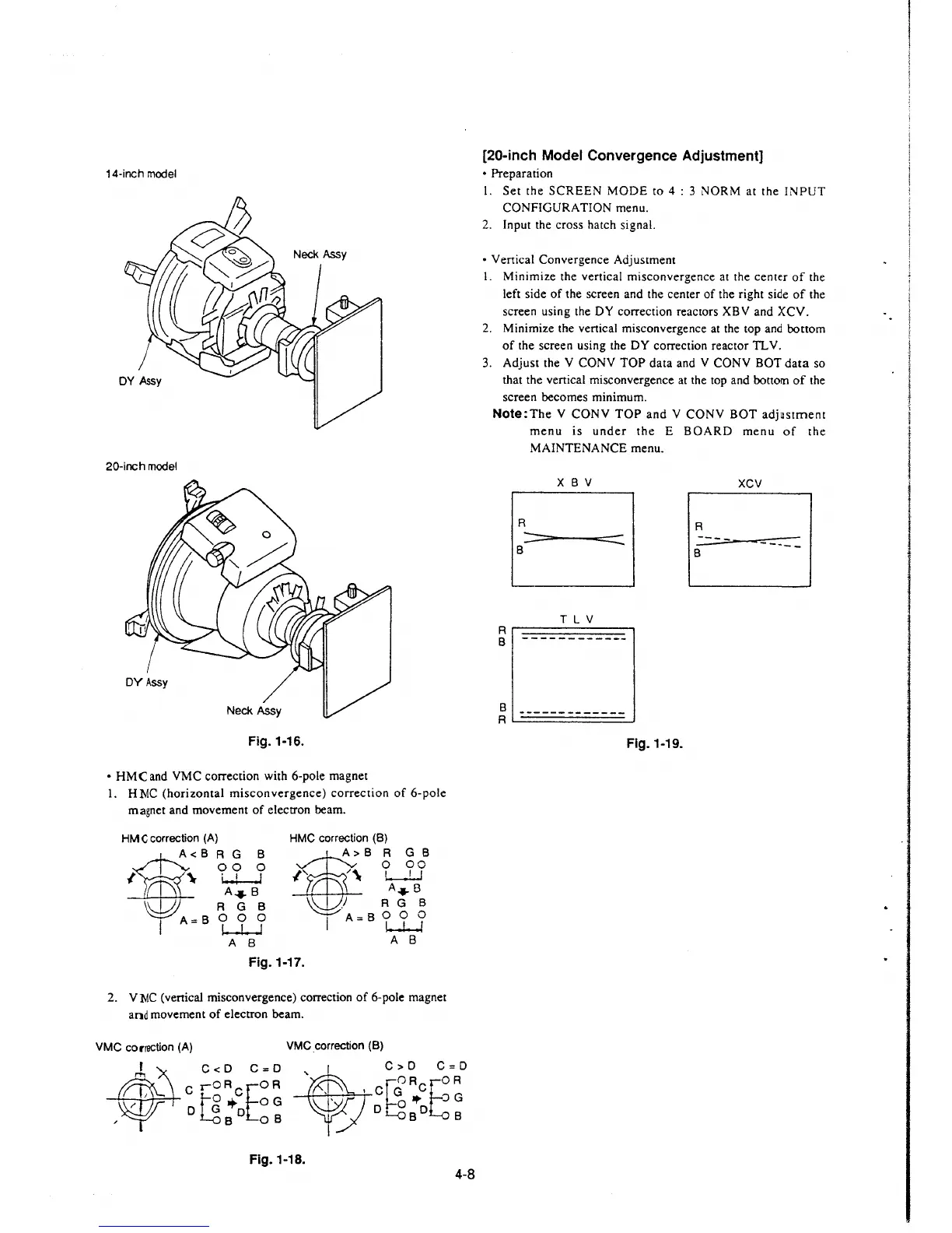
14-inch model
DY Assy
20-inch model
Neck Assy
Neck Assy
Fig.1-16.
• HMC and VMC correction with 6-pole magnet
1. H NC (horizontal misconvergence) correction of 6-pole
magnet and movement of electron beam.
HMCcorrection
(A)
HMC correction (B)
A<B ~g
~
" W--J
A-4--8
\\ I JI R G B
1A=Bt1.j
~B?A}i
-w-RGB
A B
Fig.1-17.
I
A=B000
~
A B
2. VNC (vertical misconvergence) correction of 6-pole magnet
and movement of electron beam.
VMC correction (A) VMC correction (B)
I
C<D C=D
~
C>D C=D
' OR OR
c ,oRcEoR , , c~ cE
I]
+ OG
~
o• OG
D D D BO B
B OB
Fig.1-18.
4-8
[20-inch Model Convergence Adjustment]
• Preparation
I. Set the SCREEN MODE to 4 : 3 NORM at the INPUT
CONFIGURATION menu.
2. Input the cross hatch signal.
• Vertical Convergence Adjustment
I. Minimize the vertical misconvergence at the center of the
left side of the screen and the center of the right side of the
screen using the
DY correction reactors XBV and XCV.
2. Minimize the vertical misconvergence at the top and bottom
of the screen using the
DY correction reactor TL V.
3. Adjust the V CONY TOP data and V CONY BOT data so
that the vertical misconvergence at the top and
bottom of the
screen becomes minimum.
Note:The V CONY TOP and V CONY BOT adjustment
menu is under the E BOARD menu of the
MAINTENANCE menu.
R
:::----
9
X B V
TL V
:::::::::::.
A r===========1
B
B
R
-------------
Fig.1-19.
XCV
A
----
-... __
B
 Loading...


