2. BK Board Adjustment
2-1. Adjust Preparation 1
Set as follows at the INPUT CONFIGURATION menu of the SETUP menu.
FORMAT .......................... COMPONENT YUV SMPTE/EBU N-10
SLOT NO ......................... 6
SYNC MODE .................. INT
Select BK BOARD DAT A LOAD from BK BOARD menu of MAINTENANCE menu and execute.
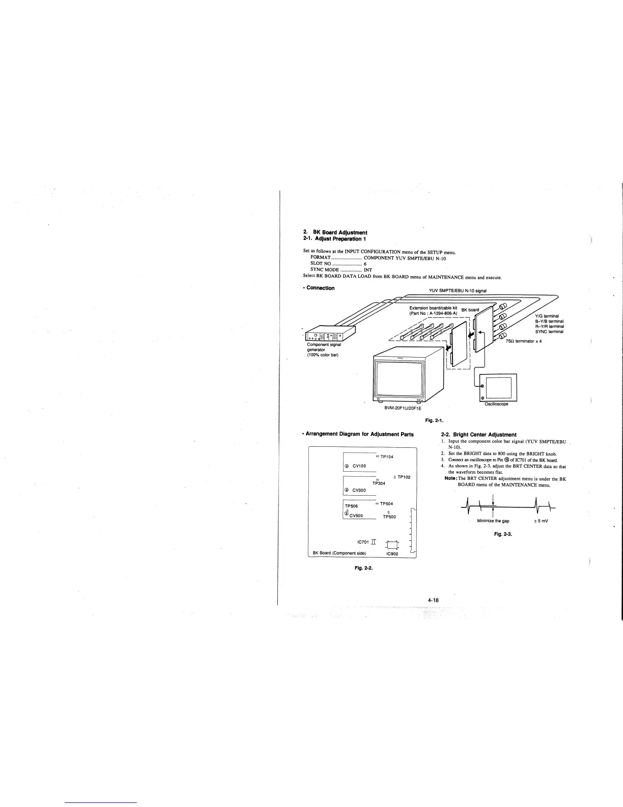
• Connection
Component signal
generator
(100% color bar)
0
BVM-20F1 U/20F1 E
• Arrangement Diagram for Adjustment Parts
D TP102
TP506
0
TP504
D
@cvsoo
IC701 'ff
BK Board (Component side)
Fig. 2-2.
0
TP500
.. D ......
f• H
IC902
Lr
YUV SMPTE/EBU N-10 signal
.D
Oscilloscope
Y /G terminal
B-Y/B terminal
R-Y/R terminal
SYNC terminal
Fig. 2-1.
4-18
2-2. Bright Center Adjustment
l. Input the component color bar signal (YUV SMPTE/EBU
N-10).
2. Set the BRIGHT data to 800 using the BRIGHT knob.
3. Connect an oscilloscope
to Pin@ofIC701 of the BK boani.
4. As shown in Fig. 2-3, adjust the BRT CENTER data so that
the waveform becomes flat.
Note: The BRT CENTER adjustment menu is under the BK
BOARD menu of the MAINTENANCE menu.
Minimize the gap
±5 mv
Fig. 2-3.
)
 Loading...


